Section 1 - Introduction
SECTION 1 Introduction
1.1 Model Profile
1.2 Using this Owner's Guide
1.2.1 Hazard Statements
1.2.2 Original Equipment Manufacturer Manuals
1.3 Trojan Owner Questionnaire
1.4 Warranty and Service Information
1.4.1 Trojan Warranty Policy
1.4.2 Warranty Registration
1.4.3 Obtaining Warranty Service
1.4.4 Second owner registration
1.4.5 Hull Identification Number
1.5 Pre-delivery Service
1.6 Owner Registration
SECTION 2 Boating Safety
2.1 Safety and Warning Labels
2.2 Safety Information
2.2.1 Safety Equipment
2.2.2 Power Transmission
2.2.3 Electrical Systems
2.2.4 Fueling and Operating
2.2.5 Electrical System Maintenance
SECTION 3 Profile
3.3.1 Hull
3.3.2 Anti-Fouling Bottom Paint
3.4 Draft
3.6 Underwater Gear
3.6.1 Propellers
3.6.2 Rudder Assembly
3.6.4 Strut Assembly
3.6.4.1 Profile and Layouts
3.6.4.2 Materials
3.6.4.3 Construction
3.6.4.4 Canvas and Upholstery
3.6.4.5 Prop Shaft and Shaft Log Assembly
SECTION 4 DC Electrical System
4.1.1 Battery Selector Switch
4.1.2 Voltmeters
4.1.4 Battery Charger
4.1.5 Inverter
4.2 Circuit Breaker Panels and Equipment
4.2.1 Remote DC Circuit Breaker Panel
4.2.2 Salon DC Circuit Breaker Panel
4.2.3 Design and Purpose
4.3 Powering 12V Equipment
4.4 12 Volt Wiring Standard
4.5 12 Volt Trouble Shooting
4.3 Battery Installation and Maintenance
SECTION 5 AC Electrical System
5.1 Using the AC System
5.1.1 Introduction
5.1.2 Reverse Polarity
5.1.3 Salon AC Panel
5.1.4 Remote AC Panel
5.1.5 Selecting a Power Source
5.1.6 50A Main Breaker
5.1.7 Connecting to Shore Power
5.1.8 Using the Onboard Generator
5.1.9 Dual Dockside Service
5.2.1 Ground Fault Interrupters
5.2.2 Electrical Loads
5.2.3 Salon AC Circuit Breaker Panel
5.2.4 Remote AC Circuit Breaker Panel
5.3 AC Generator
5.4 Air Conditioning System
5.5 Stray Current and Galvanic Corrosion
5.5.1 Stray Current
5.5.2 Galvanic Corrosion
5.6 Bonding System
5.7 AC Trouble Shooting
SECTION 6 Internal Systems
6.1 Fresh Water System
6.1.1 Fresh Water tanks
6.1.2 Fresh Water Hookup
6.1.3 Water Heating System
6.1.4 Shower
6.1.5 Water System Maintenance
6.1.6 Hand Shower
6.17 Fresh Water Washdown
6.1.8 Raw Water Washdown
6.2 Bilge System
6.2.1 Design
6.2.2 Maintenance
6.2.3 Garboard Drain
6.2.4 Bilge Pumps
6.3 Sanitation System
6.3.1 Waste Holding Tank
6.3.2 Heads
6.3.3 Winterization
6.4 Optional Sanitation Systems
6.4.1 Grey Water System
6.4.2 Overboard Discharge
6.4.3 Direct Overboard Discharge
SECTION 7 Propulsion
7.1 Engine Gauges
7.1.1 Instrument Panel Gauges
7.1.2 Gauge Maintenance
7.2 Controls and Steering
7.2.1 Transmission and Throttle Controls
7.2.2 Steering
7.3 Fuel Systems
7.3.1 Fuel Transfer Pump
7.3.2 FuelTankVents
7.4 Operating Instructions
7.3.3 Fuel Gauges
7.3.4 Gasoline Fuel System
7.3.5 Diesel Fuel System
7.3.6 Halon Fire Suppression System
7.4 Operating Instructions
7.4.1 Fueling
7.4.2 Pre-Start Checklist
7.4.3 Starting the Engines
7.4.4 After Startup
7.4.5 Getting Underway
7.4.6 The Shakedown Cruise
7.5 Trouble Shooting Gauges, Controls and Fuel System
SECTION 8 Maintenance
8.1 General Maintenance Schedule
8.2 Exterior Maintenance
8.2.1 Fiberglass Surfaces
8.2.2 Anti-Fouling Bottom Paint
8.2.3 Caulking and Sealants
8.2.4 Stainless Steel Rails and Hardware
8.2.5 Decorative Striping Tape
8.2.6 Windows
8.2.7 ExteriorVinyl Upholstery
8.2.8 Exterior Carpet
8.2.9 Exterior Painted Surfaces
8.2.10 Exterior Plexiglass
8.3 Interior Maintenance
8.3.1 Interior Woodwork
8.3.2 High Pressure Laminate
8.3.3 Woven Fabrics
8.3.4 Interior Carpet
8.3.5 Interior Fiberglass and Plexiglass
8.4 Mechanical and Electrical System Maintenance
8.4.1 Mechanical System Maintenance
8.4.2 Electrical System Maintenance
8.5 Water, Bilge and Sanitation System Maintenance
8.5.1 Water System Maintenance
8.5.2 Bilge System Maintenance
8.5.3 Sanitation System Maintenance
8.6 Lifting and Winter Storage
8.6.1 Lifting
8.6.2 Winterization
SECTION 9 Miscellaneous
9.1 OEM Suppliers List
OWNER'S GUIDE TO SAFE AND PROPER OPERATION
Sleeping capacity 4std./6opt.
Electrical system 12V DC; 120V AC
Fuel capacity 432 gallons (1635,29 I)
Fresh water capacity 104 gallons (393,68 I)
Waste system capacity 100 gallons (378,54 I)
Length overall 43'11" (13,39 m)
Length overall (w/platform) 44'9" (13,64 m)
Beam (at waterline) 12'2" (3,71 m)
(at gunwale) 15'0" (4,57)
Draft 52" (1,32 m)
Bridge Clearance (w/standard arch) 10'11" (3,33 m)
Freeboard (aft) 3'9" (1,14 m)
(forward) 5'5" (1, 65 m)
Weight (with fuel and water) 32,000 Ibs (14515,2 kg)
Dimensions
Main Cabin ( L x W x H ) 13'1" X 10' x 6'5"
(3,99 x 3,05 x 1,96 m)
Forward Cabin ( L x W x H ) 9'10" X 10' x 6'4"
(2,99 x 3,05 x 1,93 m)
Aft Cabin ( L x W x H ) 7'0 x 6'11" x 6'5"
(2,13 x 2,11 x 1,96 m)
1.2 USING THIS OWNER'S GUIDE
INTRODUCTION
We welcome you to the distinguished family of Trojan Yacht owners. Your Trojan Yacht was conceived with "human engineering" in mind. It was developed for the discriminating yachtsman to use and live in and design through assembly, inspection, and testing has been undertaken with sea worthiness, serviceability, comfort and satisfying eye appeal as major goals.
IT IS IMPORTANT THAT YOU READ AND UNDERSTAND ALL MATERIALS INCLUDED WITH THIS OWNER'S GUIDE PRIOR TO OPERATING YOUR BOAT OR ANY OF ITS EQUIPMENT.
1.2.1
HAZARD STATEMENTS
This guide was prepared and written to serve as an operations manual specifically for your 440 EXPRESS. It includes information on your boat and all its systems.
This guide is organized into ten sections, each dealing with a particular facet of your boat's operation. Detailed drawings and diagrams are also included in this guide
The Trojan Owner's Guide was also developed to enhance your boating safety. Safety precautions and operational tips have been organized in the following manner:
!DANGER!
Substantial property damage if the warning is not observed
!CAUTION!
Property damage if the proper precautions are not observed.
Describes a hazard, which can cause severe injury, death if ignored.
!WARNING!
Describes a hazard that could result in serious personal injury and/or
!CAUTION!
Describes situations that could damage your boat or its components.
NOTE: Various warnings and other important safety information are listed in SECTION 2 of this owner's guide. Please refer to pages 2.1 through 2.4 and review this information prior to operating your boat.
ORIGINAL EQUIPMENT MANUFACTURER (OEM) MANUALS
The second set of manuals that pertain to your new boat are supplied by manufacturers other than Trojan. These manufacturers are referred to as OEM suppliers
Engines, stoves, refrigerators and air conditioners are examples of this type of equipment.
The majority of Trojan's suppliers have created operators and maintenance manuals for their products. This information has been assembled and supplied to you.
Virtually all of your boat's components have their own limited warranty. Warranty registration cards have been provided for those products.
These are your materials. Use a colored highlighter to mark sections of the text that are of special interest. Be sure to supplement your guide with information on wiring or installation of additional equipment that you add to the boat during your period of ownership.
The Trojan Owner's Guide and all component manuals are a permanent part of your boat.
These materials must remain on the vessel during its operation. These materials must also be transferred to the boat's subsequent owners.
Trojan Yachts installed a variety of equipment, which was manufactured by OEM suppliers.
NOTE: Information presented in OEM suppliers literature and manuals takes precedence over information presented in this Owner's Guide. If there is a discrepancy between the Owner's Guide and an OEM supplier's manual, FOLLOW THE INSTRUCTIONS IN THE SUPPLIER'S MANUAL.
Information contained within this Owner's Guide is the most accurate information available at the time of publishing. Trojan reserves the right to change without notice materials, part numbers, specifications or system designs.
1.4 WARRANTY AND SERVICE INFORMATION
1.4.1 TROJAN WARRANTY POLICY. Many of the complex components (engines, generators, stoves, etc
Trojan warrants every boat we manufacture as detailed in the Trojan Limited Warranty
Document. Your copy of the Trojan Limited Warranty appears in Section 1.4 of this guide
Please review this document carefully.
The warranty on your new Trojan is the joint responsibility of the Trojan Yachts, your Trojan Dealer and yourself. All three parties have certain responsibilities to ensure that the warranty remains in force document that is included within this Owner's Guide.
Trojan Dealer Responsibilities:
The Trojan Dealer will review the terms of the warranty and make certain the warranty is registered with Trojan.
Your Trojan Dealer will instruct you on how to obtain warranty service.
The Trojan Dealer will prepare your boat for delivery in accordance with the procedures detailed on the Pre-Delivery Service Record. Your dealer will sign the
Pre-Delivery Service Record and provide you with a copy.
A representative from your Trojan Dealership will conduct a review of how your boat and its systems operate.
The Owners Responsibilities:
Make certain the boat's pre-delivery service record has been completed and mailed to Trojan.
Read and follow all OEM supplied materials. Complete and mail all OEM warranty cards.
Review the Pre-Delivery Service procedure with your dealer Pre-Delivery Service Record. Be certain you sign a copy of the Pre-Delivery Service Record and retain a copy for your records.
At time of delivery, make a complete inspection of the boat and its systems. Document any work that needs to be completed by the dealer in order to met the terms of your agreement.
Read, understand and follow the Trojan Owner's Guide and all materials contained within the Captain's Kit. Contact your dealer if you have any questions. Perform all maintenance in accordance with the operator and service guides. Systems are warranted by their respective manufacturer resolve problems with their products. Your Trojan Dealer can implement these services for the Pre-Delivery Service Record must. Your Trojan Dealership is staffed with knowledgeable professionals who are familiar with your boat and are capable of providing the highest level of service. The Trojan Dealership service personnel will communicate with The Trojan Yachts to ensure you fast and satisfactory solutions to any problem that may arise A "Second Owner Registration Card" has been provided in Section 1.4. The purchaser of Registration of a "pre-owned" Trojan does not extend or in any way modify a boat's original limited warranty. However, purchasers of a pre-owned Trojan can and should register ownership with Trojan. Having this information on file will benefit you should Trojan ever need to contact you.= Signifies that the boat was made by the Trojan Yachts. Every boat manufacturer in= Shows that the boat is a Trojan model 440 EXPRESS. Every different model made= These three positions indicate the boat's hull number. 101 shows that his boat was= This letter denotes the month the hull was molded. "A" signifies January, "8" February= This is the CALENDAR YEAR the boat was made. This boat was made in 1995.= These numbers show the MODEL YEAR of the boat the first one made as a 1996 model.
1.4.4 SECOND OWNER REGISTRATION
A "pre-owned" Trojan should complete this card and submit it to the Trojan Yachts, 1651
Whitfield Ave., Sarasota, FL 34243.
1.4.5 HULL IDENTIFICATION NUMBER (HIN)
The United States Coast Guard has established a universal system of numerically identifying vessels by using a hull identification number or "HIN." This number identifies a boat's make, model, hull number, month, and year of manufacture.
The HIN is found on a boat's transom. Look for it on the starboard side, just below the rub rail or on the transom platform.
Provide your Trojan Dealer with your boat's HIN when contacting them for parts or service.
The HIN consists of 12 alpha or numeric characters.
A typical HIN for a 1995, 440 EXPRESS will read TRJ-EA 1010596.
TRJ the United States has their own three letter designation.
EA by Trojan has its own two digit identifier.
101 the first boat of this model manufactured during this model year. A and so on.
Looking at our HIN example of TRJ-EA 1010596, we see that this boat is a Trojan EXPRESS, is a 1996 model, and that the hull was completed in April 1995. This boat was
1.5 PRE-DELIVERY SERVICE
Your Trojan Dealer will perform a thorough review of your boat and its systems commissioning of the craft. The Trojan Pre-Delivery Service Record serves as a checklist in performing this Pre-Delivery Inspection. Review this completed document with your dealer at the time you take delivery of your boat. Your Trojan Dealer will be happy to explain any of the items or procedures included in the Pre-Delivery Inspection.
The Pre-Delivery Service Record requires the owners signature. Sign this form upon accepting delivery of your new boat. In some cases there may be items that need to be remedied by the dealer after taking delivery. Make a note of these problems and attach a copy to the Pre-Delivery Service Record. This will ensure that these items will be corrected within the terms of the one year limited warranty.
This Pre-Delivery Service Record is a multi-part form. Your dealer will provide you with a copy of this form upon completion of the Pre-Delivery Inspection. Keep your copy of the Pre-Delivery Service Record with your boat's permanent records.
WARRANTY AND SERVICE INFORMATION
REGISTRATION CARDS:
Trojan warrants every boat we manufacture as detailed in the Trojan Limited Warranty Document. Your copy of the Trojan Limited Warranty appears after this page. Please review this document carefully.
The warranty on your new Trojan is the Joint responsibility of Trojan Yachts, your Trojan Dealer and yourself. All three parties have certain responsibilities to ensure that the warranty remains in force. Trojan's responsibilities are outlined in the limited warranty document that is included within this Owner's Guide.
The Trojan Dealer will prepare your boat for delivery in accordance with the procedures detailed on the Pre-Delivery Service Record. This document is found on the preceding pages. The terms of Pre-Delivery include proper registration by completing and signing the service record. Your dealer Pre-Delivery Service Record and provide you with a copy.
This card is a Second Owner Registration Card. The buyer of a previously owned Trojan
can and should register ownership with Trojan.
SECOND OWNER WARRANTY REGISTRATION CARD
Owner's Name:
Would you like to receive future promotional literature from Trojan? Yes No
New owner or selling dealer must complete and mail this registration card to Trojan Yachts
at time of delivery your Trojan Dealer.
(1) year from the date the(2) years from the date the-the first retail purchaser, and five (5) years from the date the product is delivered to the first retail purchaser.limited warranties run concurrently.obligation and the buyer's sole and exclusive remedy against the Manufacturer for breach of express warranty shall be to repair or replace defective parts, free of charge, to the purchaser. These limited warranties are subject to the following terms and conditions: Manufacturer's solenot demanded already. Proper warranty registration is strongly advised. A pre-delivery service record form is furnished with each new boat and is used for the initial warranty registration. This form must be completed by the Authorized Trojan Dealer, signed by the first retail purchaser at the time the boat is delivered and returned to Trojan. A replacement form can be obtained by contacting Trojan at the address indicated below. In order for this Trojan limited warranty to be transferred. subsequent owners must fill out and send to the Manufacturer the Pre-Owned Trojan Ownership Registration Card. or provide to the Manufacturer. in writing. the hull serial number. owner's name and address. date of subsequent purchase. and name of person from whom the boat was purchased.
A division of Carver Boat Corporation
P.O. Box 1010, Pulaski, WI 54162-1010
414-822-3214
WHAT IS COVERED
LIMITED WARRANTY ON NEW TROJAN YACHTS
Trojan Yachts ("Manufacturer") warrants to the first retail purchaser of its boats ("Product") purchased from an authorized Trojan dealer, and properly registered subsequent purchasers, as follows:
1. Should the Product, or any part thereof, be proven to have non-structural defect in material or workmanship, when used under normal operating conditions, Manufacturers will make the non-structural repairs (or, at its sole discretion replace the affected part) for a period of one year after product is delivered to the first retail purchaser, and
2. Should the Product be proven to have blistering of the hull laminate, attributable to water penetration of the gel coat (osmosis), Manufacturer will make repairs for a period of two years. product is delivered to
3. Should the Product be proven to have structural defect in material or workmanship to the hull, when used under normal operating conditions, Manufacturer will make the structural repairs for a period of three years
Product to discover all defects in material or workmanship and notify the Manufacturer or the selling dealer of same. During the warranty period, warranty repairs will be made at the dealer's store or service facility or, at Manufacturer's election, by Manufacturer at its factory, or other location authorized by Manufacturer. Transportation to and from Manufacturer's desilmated repair facility shall be at purchaser's expense. Manufacturer's election to repair the defective Product or replace the defective part is the exclusive remedy and is a condition precedent to any legal or equitable action against Manufacturer. Any action for breach of warranty relating to Product must be brought within a period of sixty (60) days following Manufacturer's failure to repair the Product or replace the defective part.
WHAT IS NOT COVERED
This Warranty does not cover:
1. New Product purchased from any party other than an authorized Trojan dealer. You may verify the authenticity of a dealer by contacting the Manufacturer at (414) 822-3214;
2. Product which has been repaired or altered by persons other than Manufacturer or an authorized Trojan dealer, without written authorization of Manufacturer, or altered in anyway so as to affect its use and operation;
3. Product which has been subjected to accident, negligence, unreasonable use, alteration, tampering, abuse, improper maintenance, mishandling, improper lifting or trailering, or used for racing or commercial purposes, or which has been operated contrary to any printed instructions furnished by the manufacturer;
4. Dealer preparation, cleaning, final adjustments, and alignments, in preparing the Product for delivery or commissioning;
5. Engines, transmissions, outdrives, and other equipment or accessories for which separate warranties are provided by other manufacturers;
6. Window glass and windshield glass breakage;
7. Fit and adjustment of exterior canvas tops, enclosures, and weathercovers;
8. Sacrificial deterioration of anti-fouling paint, or zinc anodes;
9. Equipment not purchased or installed by Manufacturer;
10. Any representation relating to the speed, range, or performance of the Product;
11. Loss of time, loss of use, inconvenience, travel expense, transportation costs, towing, or other matters not specifically covered hereunder;
12. Any act of God.
This warranty gives you specific rights, and you may also have other rights which vary from state to state. This warranty is governed by the laws of the State of Wisconsin. This document contains the entire warranty given by Manufacturer and there are no terms, promises, conditions or warranties other than those contained herein. No oral or written information or advice given by Manufacturer, its dealers, representatives, agents or employees shall create a warranty or in any way increase the scope of this warranty. Manufacturer does not authorize any person to extend the time of this warranty or to create or assume for it any other obligation or liability with respect to its Products. No person. including a dealer. i make any repairs or replacements under this warranty without the prior written a12Proval of Manufacturer. Manufacturer reserves the right to make product improvements through changes in design, material or parts without being obligated to incorporate such changes in Products previously manufactured. This warranty is not transferrable or assignable except as specifically provided below.
THIS EXPRESS WARRANTY IS IN LIEU OF, AND MANUFACTURER DISCLAIMS, ANY AND ALL OTHER WARRANTIES, EXPRESS, IMPLIED OR STATUTORY, WHATSOEVER INCLUDING, WITHOUT LIMITATION, ANY IMPLIED WARRANTIES UNDER THE UNIFORM COMMERCIAL CODE, ANY IMPLIED WARRANTY OF MERCHANTABILITY AND ANY IMPLIED WARRANTY OF FITNESS FOR A PARTICULAR PURPOSE. THIS WARRANTY SHALL BE THE SOLE AND EXCLUSIVE REMEDY OF ANY PERSON, WHETHER IN CONTRACT, TORT OR OTHERWISE AND MANUFACTURER SHALL NOT BE LIABLE FOR CONSEQUENTIAL, SPECIAL OR INCIDENTAL DAMAGE, LOST PROFITS, INCONVENIENCE, OR DAMAGE RESULTING FROM A BREACH OF THE EXPRESS OR ANY IMPLIED WARRANTY WHICH IS NOT DISCLAIMED HEREIN NOR FOR ANY OTHER LOSS OR DAMAGE, EXCEPT AS SET FORTH ABOVE.
Some states do not allow limitations on implied warranties, or the exclusion or limitation of incidental or consequential damages, so the above limitations or exclusions may not apply to you. In the event that implied warranties are non-disclaimable, those warranties are disclaimable to the extent permitted by applicable law, and all remaining implied obligations and warranties, are limited in duration to a period of one (1) year or such shorter period as permitted by applicable law.
WARRANTY REGISTRATION
LIMITED WARRANTY
Registration of your boat and its engines is also required by the Federal Safe Boating Act of 1971. Your Trojan Dealer will complete and mail your engine warranty cards as part of the Pre-Delivery Service procedure. Many of the other complex components installed on your boat must also be registered with their respective manufacturer. Warranty cards have been assembled and are contained in the OEM SUPPLIED MATERIALS packet that is part of your Captain's Kit.
ALL WARRANTY CARDS MUST BE COMPLETED AND FORWARDED TO THE APPROPRIATE COMPANY WITHIN 5 DAYS AFTER TAKING DELIVERY OF YOUR TROJAN.
OBTAINING WARRANTY SERVICE
The following requirements must be met before warranty work can be performed on your boat.
1) Your boat must be registered with Trojan Yachts. Registration is accomplished by completing and submitting the Pre-Delivery Service Record to the Trojan Yachts, 1651 Whitfield Ave
2} Pre-Delivery Service must be completed by your Trojan Dealer. See Section 1 information concerning Pre-Delivery Service be signed by both the dealer and the owner. Your Trojan Dealer is the ONLY person authorized to approve warranty work. If warranty service is needed you MUST contact your Trojan Dealer first. There are no exceptions to this policy.
---------------------------------------------------------------
Section 2 - Boating Safety
2.1 Safety and Warning Labels
2.2 Safety Information
2.2.1 Safety Equipment
2.2.2 Power Transmission
2.2.3 Electrical Systems
2.2.4 Fueling and Operating
2.2.5 Electrical System Maintenance
2.3 Engine Exhaust
2.4 Nautical Glossary
2.1 SAFETY AND WARNING LABELS
In addition to the written safety precautions which appear in your Trojan Owner's Guide, these two pages feature safety and warning labels which are affixed throughout your boat. We recommend that you familiarize yourself with these labels and understand the potential hazards that are indicated. The following label is printed on the instrument panel and also affixed to the 110 volt distribution panel.
WARNING: GASOLINE VAPORS CAN EXPLODE BEFORE STARTING ENGINE OR GENERATOR. OPERATE BLOWER FOR 4 MINUTES AND CHECK ENGINE COMPARTMENTS FOR GASOLINE VAPORS. ALWAYS OPERATE BLOWER WHILE GENERATOR IS RUNNING AND BELOW CRUISING SPEED.
DANGER
Do Not use a boarding ladder or swim platform while engines are running or the boat is in motion.
DANGER
This engine compartment is a machinery enclosure. It contains exposed moving parts. Do Not enter this area during equipment operation unless you are a trained service technician.
CAUTION
KEEP CABIN DOOR CLOSED WHEN ENGINES OR GENERATOR ARE RUNNING.
The following label is printed on the instrument panel and also affixed to the 110 volt distribution panel.
(1) THIS APPLIANCE IS DESIGNED FOR USE WITH LPG, LIQUEFIED PETROLEUM GAS ONLY.
(2) Keep cylinder valves closed when boat Is un· attended. Close them Immediately In any emergency. It Is recommended that cylinder valves be closed when appliances are nat in usa.
(3) Be lure appliance valves are closed before openIng cylinder valve.
(4) Be sure to apply IgnlUIII source to burner before opening appliance valve.
(5) Test LPG system as recommended In sign posted In vicinity of LPG cylinder.
NEVER USE FLAME T0 TEST FOR LEAKS.
WARNING: ALWAYS PROVIDE VENTILATION WHEN STOVE IS IN USE TO REPLACE OXYGEN AND TO VENT PRODUCTS OF COMBUSTION. DO NOT USE THIS APPLIANCE FOR COMFORT HEATING.
2.2 SAFETY INFORMATION
Boating safety cannot be overemphasized. The prime prerequisites for boating safety are proper operation of your vessel, knowledge of boating regulations and other "rules of the road," and respect and understanding forthe potential hazards of boating. We strongly recommend that you take full advantage of one ofthe organizations that offer courses, information and other details that deal with all aspects of good seamanship. For your reference, included in this group are:
United States Power Squadrons
P.O. Box 30423
Raleigh, NC 27617
Telephone: 800-243-6000 (toll free)
United States Coast Guard Auxiliary
Contact your local flotilla or
Coast Guard District Headquarters
As the authority and the agency for boating regulations, the U.S. Coast Guard is always available for information and guidance. There are various publications available which deal with safety and various subjects that are or should be of concern to you as a responsible boater.
The sole responsibilityforthe safetyequipmentthatyou own and the procedures that you follow is YOURS. Every Trojan meets or exceeds all applicable NMMA (National Marine Manufacturers Association) and/or United States Coast Guard Regulations in effect on the date of manufacture.
2.2.1 SAFETY EQUIPMENT
I n addition to safety items included as standard equipment on your Trojan, we recommend that you have you r owner's man ual and man uals that cover the eng ines a nd other onboard equipment. Equip your boat to comply with U.S. Coast Guard regulations and also forthe waters in which you will be cruising.
The following is a list of the various warnings and other important information that we feel should be emphasized. Some have already been mentioned in this manual, and we list them here again for emphasis. Some are not of a hazardous nature, but all are important.
WE CAUTION THAT THIS LISTING IS NOT EXHAUSTIVE AND DOES NOT CONSTITUTE ALL OF THE "WARNINGS" OR "CAUTIONS" THAT SHOULD BE RECOGNIZED AND PRACTICED.
2.2.2 POWER TRANSMISSION SYSTEM
Always use the oil recommended in your engine and transmission manual when addition or change of oil is necessary. Failure to do so may result in damage.
Power transmission system - Diesel
It is important that engine supply and return lines are withdrawing and returning to the same tank.
It is very important that no air be allowed to get into the diesel fuel system. Air in the fuel system may result in engine shut-down and it may be necessary to reprime the engine fuel system.
Power transmission system - Exhaust Systems
In the event of "Back-fire" the entire system should be checked to make sure that all hoses and fittings are secure. Cracks in the exhaust system could release deadly carbon monoxide (CO) and water into the boat.
!DANGER!
Engine and generator exhaust systems produce colorless and odorless carbon monoxide gas. Potential prolonged exposure can result in carbon monoxide poisoning which may be harmful or fatal. In order to prevent excessive exposure and reduce the possibility of the accumulation of carbon monoxide in the living areas of the boat, the operator should:
1. Operate engine(s) and/or generator only with an adequate exhaust system (no leaks). To assure this, proper maintenance and periodic inspection, even while operating, are required.
2. Whenever practical and always while underway, keep the cabin entrance door and any portholes or aft hatches closed. This is to avoid the potential for drawing exhaust fumes over the transom and forward into the boat. Provide good air flow through ventilation to enclosed living areas by opening forward windows and/or hatches.
3. Similarly, make sure that fore and aft ventilation is promoted in exterior helm areas that are either partially or fully enclosed.
4. Always have a competent person on watch (awake and alert) and monitoring all living areas for carbon monoxide whenever the engines or generator are in operation.
5. Never allow engines and/or generator to run for prolonged periods while docked or at anchor. Always operate the blowers while idling at slow speeds.
6. Use the carbon monoxide detection device following the instructions that accompany it. Monitor it at least once every hour.
7. At the first sign of an exhaust leak or any carbon monoxide accumulation, immediately evacuate and properly ventilate all enclosed living spaces. Locate the source of the problem and take corrective action.
Similarly, make sure that fore and aft ventilation is promoted in exterior helm areas that are either partially or fully enclosed.
Always have a competent person on watch (awake and alert) and monitoring all living areas for carbon monoxide whenever the engines or generator are in operation.
Never allow engines and/or generator to run for prolonged periods while docked or at anchor. Always operate the blowers while idling at slow speeds.
Use the carbon monoxide detection device following the instructions that accompany it. Monitor it at least once every hour.
At the first sign of an exhaust leak or any carbon monoxide accumulation, immediately evacuate and properly ventilate all enclosed living spaces. Locate the source of the problem and take corrective action.
2.2.3 ELECTRICAL SYSTEMS
Batteries must be handled with caution. They produce explosive gases and corrosive materials. Keep flames and cigarettes away. Ventilate when charging. Always shield eyes when working near batteries.
!CAUTION!
Negative ground system. Reversing the polarity will cause serious damage to the alternator.
Shore power cables
An incorrect shore power connection can result in serious or fatal injury. Disconnect cables and contact a qualified electrician.
Avoid making a connection to a "live" shore outlet, or any unnecessary contact with the cable in wet weather.
The ship-to-shore cables and other A.C. equipment used on your boat are the finest quality and the safest available. The current carried by this equipment can result in serious or fatal injury. Always follow recommended procedures.
!DANGER!
Avoid contact with a live cable, especially in wet weather. Never attempt to connect a live shore outlet in wet weather. Avoid wetting the cable, inputs and all other electrical equipment. Use only 3-wire grounded or double insulated appliances.
Inspect cables, appliance cords and outlets frequently. If worn, have them repaired or replaced immediately. Check specifically for deterioration or overheating. Do not use any electrical equipment that is known or suspected to be defective.
2.2.4 FUELING AND OPERATING
If the odor of gasoline is apparent at any time before or after you are underway, shut down the engines and all electrical systems and investigate the source of odor. Correct the situation before restarting.
Note: Your boat has a lazarette suitable for storage of a one or two man personal watercraft. PWCs operate on gasoline fuel. Therefore the storage space has been sealed from the rest of the hull and provided with separate ventilation. Use caution when storing gasoline in this location. Do not store gasoline elsewhere ie in the yacht.
2.2.5 ELECTRICAL SYSTEM MAINTENANCE
Be sure that all power is off when disconnecting the batteries to prevent sparks when cables are removed. Be sure that there are no gasoline fumes remaining in the bilge. It is advisable to disconnect the batteries prior to draining the fuel lines because you may have spillage.
2.3 CARBON MONOXIDE WARNINGS FOR GASOLINE ENGINES
!DANGER!
Carbon monoxJde (CO) Is a colorless and odorless poisonous gas which Is emitted In engine and generator exhaust. Prolonged exposure to CO can result In unconsciousness, brain damage, and death. In high concentrations, CO can be fatal in minutes; however, the effects of lower concentrations can be just as lethal.
Symptoms of excessive exposure to carbon monoxide are:
• Dizziness • Watering, Itchy eyes
• Drowsiness • Flushed appearance
• Nausea or Vomiting • Inattentiveness
• Headache • Incoherence
• Ringing in the ears • Fatigue
• Throbbing temples • Convulsions
Carbon monoxide accumulation requires Immediate attention! Thoroughly ventilate cabin and cockpit areas. Determine the probable source of the carbon monoxide and correct the condition immediately. Carver has installed CO detectors on your boat. Have these detectors professionally calibrated at regular intervals.
! DANGER!
Persons sleeping onboard can easily be overcome by carbon monoxide without realizing It. Sleeping while the engines or generator are running is NOT recommended. To help preterit carbon monoxide accumulation, ventilate your cabin and cockpit while underway. Open a forward hatch, porthole, or window to allow air to travel through the boats interior.

Have a trained marine technician inspect the boat's exhaust systems whenever the boat is in for service or if you notice a change in the sound of an engine or generator. Maintain proper engine adjustments, condition, and performance.
The following page describes some possible situations where CO may accumulate. 8ecome familiar with these examples and the suggested precautions to help prevent a dangerous accident.

2.4 DEFINITIONS OF TERMS
While reading your Owner's Guide you will encounter many descriptive terms that are unique to seamanship and yachting. The following summary defines these terms as they are used within this
Owner's Guide.
ABAFT -Toward the rear ofthe boat.
ABEAM - At right angles to the boat's keel.
ABOARD -On the boat.
ABREAST - Side-by-side.
ADRIFT - Loose, not on a mooring ortow line.
AFT - Moving toward the stem.
AGROUND - Stuck fast on the bottom.
AHEAD -In a forward motion.
AMIDSHIP -1) An object or area midway between the bow and stern of the boat. 2) An object or area midway between the port and the starboard side of a boat.
AMPERE -The standard unit to measure the strength of an electrical current.
ASTERN -In the back ofthe boat.
BEAM -1) The widest distance across a boat. 2) A transverse structural member that stiffens and supports a portion of the deck.
BILGE - The lowest interior area of a boat's hull, used to collect water that has drained into or entered the vessel.
BILGE PUMP - A pump intended for removal of water that has drained into the boats bilge.
BOW -The front end of a boat.
BOW LI NE - A docking line leading from the boat's bow.
BREAKER - See "circuit breaker".
BRIDGE -The uupper most" steering station from which the vessel is controlled.
-------------------------------------------------------
Section 3 - Profile
3.1 Profile and Layouts
3.2 Materials
3.3 Construction
3.3.1 Hull
3.3.2 Anti-Fouling Bottom Paint
3.4 Draft
3.5 Canvas and Upholstery
3.6 Underwater Gear
3.6.1 Propellors
3.6.2 Rudder Assembly
3.6.3 Prop Shaft and Shaft Log Assembly
3.6.4 Strut Assembly
MODEL PROFILE


3.2 MATERIALS
The hull, deck and shower stalls, are made of molded fiberglass. Many of the fiberglass parts in your boat are further reinforced by laminating core materials between layers of fiberglass.
The exterior or exposed surface of many fiberglass parts is coated with a layer of gel coat. Below the waterline hull surfaces have a layer of vinyl ester under the gel coat.
The exterior walking surfaces of your boat have been textured with non-skid. This provides a solid footing surface on the boat's deck, walkways, ladder steps and swim platforms.
Information on how to maintain the fiberglass surfaces of your boat is included in Section 8.3 of this Owner's Guide.
Several different types of wood are used in your 440 EXPRESS.
Several carefully selected types and thicknesses of premium quality, exterior grade fir plywood are used throughout your boat to construct and reinforce a variety of components. High grade mahogany lumber is used in areas that provide structural strength to the boat and interior framework.
Stainless steel and aluminum are used throughout your 440 EXPRESS These metals provide high strength-to-weight ratios, are non-magnetic, and are highly resistant to moisture.
The safety rails on the 440 EXPRESS are welded from stainless steel rail. Information on how to care for the rails and hardware of your boat can be found in Section 8.3 of this Owner's Guide.
HPL is used within the 440 EXPRESS to surface bulkheads, cabinets and counter tops. These laminates are selected for their strength and durability, are easy to clean, and add colorful highlights to the inside of your boat. Information on cleaning your boat's HPL surfaces will be found in Section 8.4 of this Owner's Guide.
Formed plastic is used in a variety of ways throughout the interior and exterior of your boat. Plastic offers a high strength-to-weight ratio and excellent resistance to the affects of moisture.
A few of the areas where formed plastics are used are in the boats water and sanitation tanks, bridge seat forms, interior mirrors and in electrical circuit breaker panels. Information on cleaning the plastic and acrylic panels is included in Sections 8.3 and 8.4 of this Owner's Guide.
A wide variety of fabrics can be found throughout the interior and exterior of your boat. Woven fabrics are used for interior mattresses and chairs, and vinyl fabrics are used for exterior cushions and helm seats.
The vinyl coating of the interior wall coverings and headliner makes them easy to clean.
The carpet and fabric selected for your boat are of premium grade and have been treated with a popular stain resistant product.
3.3 CONSTRUCTION
3.3.1 HULL
Your 440 EXPRESS was built using a modular construction technique. This method of building boats uses the physical properties of many components to add strength and rigidity to the boat's hull and deck. The interior liners of the boat are securely bonded to the hull and deck to increase strength while minimizing the boat's overall weight.
The hull is made of numerous layers of various types of laminated fiberglass. Its strength is derived from laminating several carefully selected, hand laid layers of fiberglass material that have been impregnated and bonded together with polyester resin. Your hull does not contain any balsa wood coring materials. The actual thickness of your boat's hull varies depending upon the structural requirements of a particular area. The thickness, however, generally increases as you go from the sheer to the keel area of the hull.
I CAUTION I
DO NOT Install an Item Into or through the hull without sealing the area penetrated by the fastener or fitting. Improper or Inadequate sealing may lead to hull leaks or serious hull damage. Consult your TROJAN Dealer for recommendations on what type and brand of sealer to use.
3.3.2 ANTI-FOULING BOTTOM PAINT
The underwater surfaces of your boat are coated with a high quality coat of anti-fouling bottom paint. Trojan uses Rule KL-990 Epoxycop, a tough, abrasion resistant paint for moderately fouling water conditions. The paint has a high copper load and anti-fouling elements that will retard the growth of marine life on the bottom of your boat's hull. The paint's anti-fouling agents have a lifespan of about twelve months. Trojan suggests that you repaint the hull with a fresh coat of bottom paint on an annual basis. To avoid compatibility problems, be sure to use the same brand of paint originally applied to the boat. Failure to do so can void your bottom paint warranty.
To prep the boat for painting, lightly rough up the existing paint with 80 or 100 grit sandpaper. Paint can be applied by brush, roller, or spray. For severely fouling conditions, apply an additional medium to heavy coat of KL-990 Super Epoxycop manufacturer's #K-62 black. For multiple season protection in moderately fouling waters, apply an additional medium to heavy coat of KL-990 Epoxycop (manufacturer's #K-52 black). For both products, if two coats are applied, allow 3-6 hours drying time between coats. KL-990 paints are available through most marine distributors nationwide.
3.3.3 INTERIOR MODULES
Major components and cabin modules are built separate from the hull and deck arid are fitted into the hull before the deck is positioned and secured. Modules are designed to work with the hull and deck to strengthen the boat.
3.3.4 DECK
The deck of the TROJAN 440 EXPRESS uses a complex system of laminated fiberglass to give it the ability to support the superstructure of the boat.
All exterior surfaces, including the non-skid areas are coated with pigmented gelcoat. Where equipment and hardware are fastened, wooden or metal backing plates are used. Many of these backing plates can't be seen on a completed boat because they are actually laminated into the fiberglass. High stress area~ receive additional layers of fiberglass laminates as reinforcement.
The hull and deck are fastened together using the TROJAN ·shoe boxN hull-to-deck joint. This joint creates a strong and highly water tight union between these two critical components of your boat

3.4 DRAFT
A draft of 52" (1,22 m) has been calculated based upon the boat's 28,000 Ib (12 700,80 kg) dry weight. Draft is the depth of water from the water line to the lowest point on the boat, usually the bottom tip of the props.
The draft of a boat will vary depending upon the salinity of the water, the amount of equipment on the boat, the capacity of the fuel, water and waste tanks as well as the number of people on board. Due to these variables, the draft of your boat should be checked when the boat is fully equipped and loaded.
Sheer to Waterline Draft
43" (144,78 cm) 52" ( 121,92 cm)
42" (142,24 cm) 53" ( 124,46 cm)
41" (139,70 cm) 54" (127,00 cm)
40" (137,16 em) 55" ( 129,54 em)
39" (134,62 cm) 56" ( 132,08 em)
Dry weight does not include fuel, water, optional equipment, food, beverages, safety gear or anything else a family is likely to have aboard their boat. The actual weight of your boat will be greater than the dry weight figure listed here.
The approximate weight of your boat can be estimated when the actual draft is known. It will require approximately 2,250 Ibs (1020,60 kg) to increase a 440 EXPRESS's draft by 1" (2,54 cm). If a 440 EXPRESS draws 53" (134,62 cm) at its dry weight of 28,000 Ibs (12700,80 kg), a boat that draws 55" (139,70 cm) will weigh approximately 32,500 Ibs (14742,00 kg).
55"- 53" = 2" X 2,250 Ibs = 4,500 Ibs + 28,000 Ibs = 32,500 Ibs est. total weight
(139,70 cm -134,62 cm = 5,08 cm X 1020,60 kg = 2041,20 kg + 12700,80 kg =
2,54 cm
2,54 cm
14 742,00 kg est. total weight.)
This computation is for estimating purposes only. Use it to generate a rough approximation of your boat's total weight.
The 2,250 Ibs (1020,60 kg) figure used for this draft/weight computation is unique to the shape of the 440 EXPRESS's hull. You can not use this figure on boats other than the 440 EXPRESS.
Excessive weight in the fore or aft sections of the boat will cause a trim change and may yield greater draft than expected. Equip your boat with a good quality depth instrument and allow ample water below the hull while operating.
3.6 UNDERWATER GEAR
3.6.1 PROPELLERS
Your boat is equipped with two propellers. These props are counter-rotating to provide maximum maneuverability and efficiency. Each prop is designated for either right-hand or left-hand rotation.
Propellers come in a wide variety of shapes and sizes to meet the needs of different performance requirements. The actual size and type of propeller used on your boat has been listed on the Pre-Delivery Service Record and the Select Bills of Material found in Section 9.
A basic knowledge of how a propeller works will allow you to better understand the terminology used to describe the aspects of propeller performance.
Diameter - Diameter is twice the distance from the center of the prop shaft to the extreme tips of the propeller blades. Increasing or decreasing the diameter of a prop will have a direct bearing on the RPM that the engines will be capable of developing. This is because changing the blade size changes the amount of blade surface that comes into contact with the water.

Pitch - Pitch is a measure of the helix angle (or angle of attack) of the rotating blade. Pitch can be better understood by imagining the propeller rotating through a semi-solid medium such as butter. The distance (in inches) the propeller will travel in one revolution corresponds to the props pitch. Increasing or decreasing pitch will have a direct bearing on engine RPM. Increasing the props pitch will allow it to take a bigger "bite", increasing the load on the engine and lowering engine RPM.

Prop Slip - A propeller operating in a low viscosity fluid such as water is subject to a certain amount of slip. The difference between a prop's theoretical "bite" and its actual "bite" is referred to as prop slip.
Prop slip is expressed as a percent of the computed theoretical speed. Twenty-five to thirty-five percent slip is quite common for a large boat operating at normal cruising speed.
Changing either the diameter or pitch of a prop will have an effect on engine speed and prop slip. The propellers that Trojan has selected and included with your boat will provide the best overall performance and efficiency under normal conditions and loads. This has been determined by data obtained through on-water testing.
Under normal conditions the engines should turn within the RPM range listed by the engine manufacturer. If the engines exceed this range a change in prop diameter or pitch may be required. Changes to your boat's propellers should only be made by a qualified individual. See your Trojan Dealer before changing or making adjustments to your boat's propellers.
3.6.2 RUDDER ASSEMBLY
Rudders are used to control the direction of the boat while underway. Your boat uses two external rudders. The rudder shafts enter the hull of the boat through a rudder port which is well above the normal waterline. The higher rudder ports and close fitting bearings are enough to keep water from entering the boat. The rudder port system requires no adjustment or maintenance. Rudder movement is controlled through the boat's hydraulic steering system. The boat will turn when water strikes the rudders at an angle. Additional information regarding the steering system can be found in Section 7.2 of this Owner's Guide.
3.6.3 PROPELLER SHAFT AND SHAFT LOG ASSEMBLY
Propeller Shaft - The propeller shaft connects the propeller to the engine output shaft. This shaft is made of a special stainless steel material to exact tolerances. A shaft that is not straight or not in perfect balance will create vibrations that may damage certain propulsion system components.
The propeller shaft MUST be properly aligned between the engine output flange, shaft log and struts in order for it to rotate smoothly. Your Trojan Dealer aligned your boat's propeller shafts as part of the Pre-Delivery Service. We recommend that you have your Trojan Dealer check the shaft alignment after your engines have been run for 25 hours. Alignment must also be checked on an annual basis and/or every time the boat is lifted and launched.
Proper and precise shaft alignment is critical and should be left in the hands of an experienced marine technician.
Once a shaft has been damaged, it is very difficult to repair. Trojan recommends replacing damaged shafts instead of attempting repairs.
Shaft Log - Your boat is equipped with Norscot® propeller shaft seals. Periodically check the tubing connected to the seal. If transmission fluid is not visible in the tube, the seals are not being lubricated. Add ATF Dextron II fluid as necessary.
If a propeller shaft needs to be removed, drain the lubricant by removing the brass drain plug on the bottom of the shaft seal housing. Remove the sight gauge tube from the fittings at the top of the shaft seal housing. Pull the propeller shaft. Loosen the hose clamps and remove the shaft seal assembly.
To reinstall the shaft seals see the re-installation instructions found in the OEM instructions. Contact your dealer if you have any questions regarding the Norscot® propeller shaft seal.
3.6.4 STRUT ASSEMBLY
Struts are fastened to the boat's hull and are used to support the propeller shaft. The
440 use both primary and intermediate struts. Primary struts are the larger aft most
struts. Intermediate struts are installed between the primary strut and the shaft log.
The 440 EXPRESS uses 900 struts. Using 900 struts allows an individual strut to be used on either the port or starboard side of the boat. This makes carrying a spare strut easier and more economical.
A rubber bearing within each strut provides a smooth surface on which the propeller rotates.


------------------------------------------------------------
Section 4 - DC Electrical Systems
SECTION 4 DC Electrical System
4.1 Design and Purpose
4.1.1 Battery Selector Switch
4.1.2 Voltmeters
4.1.3 Powering 12V Equipment
4.1.4 Battery Charger
4.1.5 Inverter
4.2 Circuit Breaker Panels and Equipment
4.2.1 Remote DC Circuit Breaker Panel
4.2.2 Salon DC
4.3 Battery Installation and Maintenance
4.4 12 Volt Wiring Standard
4.5 12 Volt Trouble Shooting
4.1 DESIGN AND PURPOSE
Your TROJAN 440 EXPRESS is equipped with a 12 Volt DC
Wire-runs and connections are positioned to prevent abrasion and exposure to moisture, as well as to remain accessible for inspection, repairs and addition of electrical components. Electrical wire used throughout your boat is plastic coated, color-coded wire. A guide to the color code system used by Trojan can be found in Section 4.4. Connections are made using crimped connector points.
Your boat's electrical system is virtually maintenance free, with only the batteries requiring periodic inspection and maintenance.
4.1.1 BATTERY SELECTOR SWITCH
The Direct Current electrical system is powered by two heavy duty D8 batteries. The batteries are firmly anchored outboard of the port engine. Refer to Section 8.4 for battery maintenance.
The power within these batteries is controlled by the battery selector switch which is located below the helm seat on the cockpit panel. The battery selector switch acts as a master disconnect as well as a selector switch for either the STARBOARD battery, the PORT battery, or both batteries together.
With your battery selector switch in the OFF position, all 12V power is disconnected from all equipment except the bilge pumps and voltmeters. When the switch is in the BOTH position, the electrical power is being supplied by both batteries.
Use both batteries to start your engines when both batteries have a charge of less than 11 volts. This is the only time you should use the BOTH position. Start one engine with the selector in the BOTH position, when the engine is running smoothly, switch to STARBOARD or PORT and start the other engine. The engine which is running will generate enough charge to start the other engine.
Alternating the use of your two batteries will prolong their life.
The 440 EXPRESS is equipped with a momentary starting parallel system which connects both port and starboard batteries thru a momentary solenoid while cranking. The port and Starboard engine disconnects are located in the engine compartment. These switches disconnect all of the engine's electrical systems only.
! CAUTION!
NEVER turn the battery selector switch to the "OFF" position while an engine or engines are running. Doing this will damage the alternator or engine wiring.
4.1.2 VOLTMETERS
When Starting Your Engines
! DANGER!
Read, understand and follow the procedures described in Section 7.3 of this
Owner's Guide before starting your boat's engines. Improper starting procedures can create hazardous situations.
! CAUTION!
TURN OFF all electronic communication and navigation equipment PRIOR TO starting the boat's engines. The large swing in the current supply during engine start-up can damage electronic equipment.
1) Activate the voltmeter by making sure the circuit breakers marked VOLTMETER are in the ON position. These breakers are located on the battery selector switch panel.
2) The voltmeter is installed on the main load panel above the salon lounge aft. Look at the voltmeter to determine which battery has the LOWEST available voltage. The voltmeter is activated by the switch that is installed immediately below the voltmeter.
Toggle the voltmeter switch to PORT or STARBOARD.
3) If your voltmeter shows that one battery has a lower level of charge than the other, switch the battery selector switch to the battery that has the HIGHEST available voltage.
4) Start one of the boat's engines. When it is idling smoothly, start the remaining engine. Start each engine independently. Never try to start both engines at once.
5) After the engines are running, switch the selector switch to the battery bank that had the LOWEST voltage reading. This will allow the engine's alternator to recharge the low battery. Refer to 4.1.1 for information on operating the battery selector switch.
The voltmeter reads static voltage-when the engines are off. When the engines are running, one battery will indicate a higher reading than the other. This is because the voltmeter reads alternator charging rate when the engines are running. The position of the battery selector switch determines which battery will be charged by the alternator.
4.1.3 POWERING 12V EQUIPMENT
Using the DC electrical system requires thoughtful power management practices. Even with the engines running, it is possible to use all the power the alternators generate. Do not operate lights or other DC loads unnecessarily. Check the power usage periodically, especially if the engines are not running.
Without an engine running, a battery will discharge as it powers 12 volt equipment. Operating 12 volt equipment without charging a battery will eventually completely discharge the battery. Using only one battery at a time will allow you to totally discharge that battery and keep the other battery in reserve to start the engines.
Fully charged batteries that have not been charged or discharged for at least 2 hours should indicate between 12.3 to 12.6 volts. A reading below this level indicates a partly discharged battery.
4.1.4 BATTERY CHARGER
Your 440 EXPRESS is equipped with an 80 Amp battery charger. The battery charger uses AC power to recharge the 12 volt batteries. The battery charger is installed on the engine compartment's forward and starboard bulkhead.
Provide AC power to the battery charger by turning the AC breaker labeled BATTERY CHARGER on the cockpit panel to the "ON" position.
When activated, the battery charger automatically monitors the charge of both engine and generator batteries, regardless of the position of the battery selector switch. When the voltage in a battery drops below a predetermined level, the charger automatically recharges the low battery.
The battery charger will charge the batteries even when the battery selector switch is in the OFF position or engine battery switches are off.
More information on using the battery charger can be found in Section 5.2.3 of this owner's guide.
4.1.5 INVERTER
Your boat is equipped with an inverter which converts 12Volt DC to 110Volt AC making it possible to operate the VCR and the television. The electrical system automatically connects the inverter to the television and stereo if the dockside wiring is not hooked up or the generator is not running. Be aware that this equipment exerts a "load" on a 12Volt electrical system when used without the engines running.
4.2 CIRCUIT BREAKER PANELS & EQUIPMENT
The12 volt Circuit Breaker Panel manages 12 volt electrical power. The 12 volt service is split between two circuit breaker panels, a remote panel below the helm seat and the main DC load center panel on the aft starboard bulkhead of the boat's salon.
At regular intervals, test the batteries' voltage by activating the test switch below the voltmeter on the salon breaker panel. This connects each battery separately to the voltmeter. Fully charged batteries should indicate between 12.3 and 12.6 volts. A reading below this level indicates a partially discharged battery.
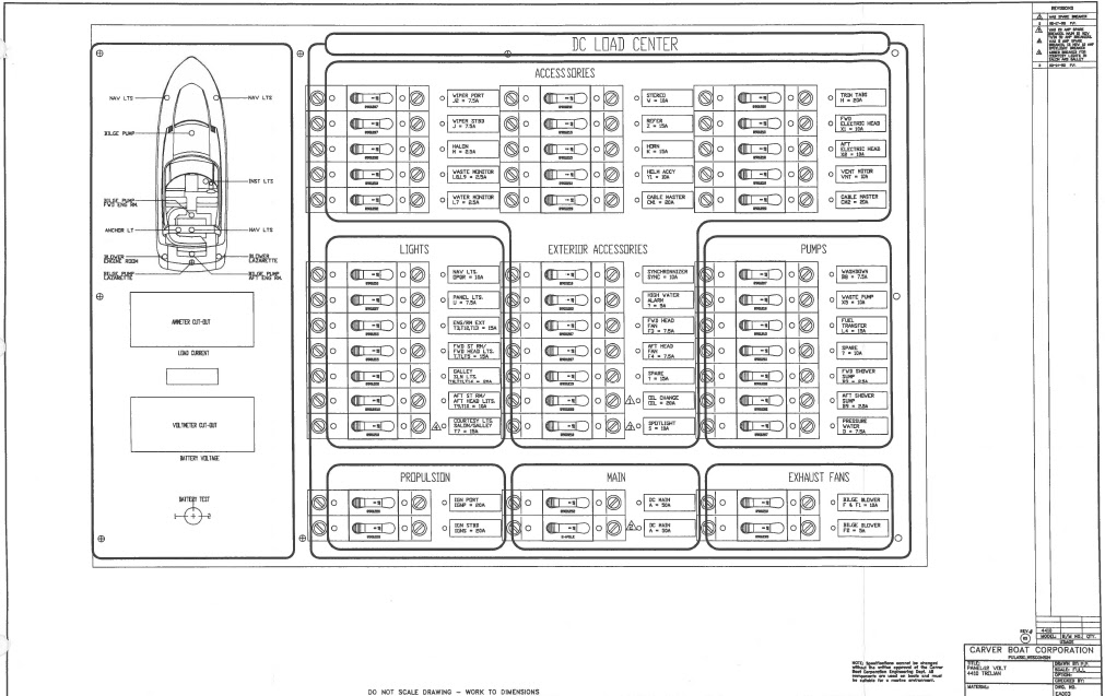
4.2.1 MAIN DC LOAD CENTER
A drawing illustrating the 12 volt circuit breaker panel in the salon appears on page 8 in this section of the Owner's Guide.
MAIN circuit group (bottom, middle)
MAIN: The 100 amp MAIN circuit breaker must be in the "ON" position in order for any other 12 volt circuit breakers to function. When leaving the boat, it is recommended that the MAIN switch be turned off. This will prevent draining the battery if any accessories were inadvertently left on. It also disconnects the ignition/start switches.
NOTE: Turning this switch off will not affect the automatic operation of the electric bilge pumps, voltmeters, battery charger or CO monitors.
SPARE: The 20 amp spare circuit breaker has been added for owner installed equipment.
LIGHTS circuit group (middle, port) - Labeled as follows:
NAV LIGHTS: Power to the navigation lights on the 440 EXPRESS is controlled by this 10 amp breaker. A switch at the helm turns the lights on or off.
PANEL LIGHTS: A switch at the helm control station turns the panel lights on and off. Power to the panel lights is controlled by this 7.5 amp breaker.
ENG/RM EXT: The 15 amp breaker controls power to the engine room lights. These are manually switched on and off at the helm station.
FWD STATEROOM L TS: This 15 amp breaker controls power to the master stateroom lights. The lights can be turned on and off by a switch on the inboard side of the vanity.
GALLEY SLN/L TS: The 20 amp breaker controls power to the lights in the galley and salon area. The lights can be turned on and off by using the switches located in the galley or salon.
AFT ST RM HEAD LIGHTS: Power to the interior lights in the boat's aft cabin is controlled by this 10 amp breaker. The lights can be turned on and off by using the switches in the aft stateroom.
SPOTLIGHT: The spotlight can be operated at the boat's helm station. Power to the spotlight is controlled by this 10 amp breaker.
PROPULSION circuit group (bottom, forward) - Labeled as follows
PORT IGN and STBD IGN: These two 20 amp breakers control the engines' ignition circuits. In addition to the 12 volt MAIN and the battery selector switch, these breakers must be turned on prior to starting the engines.
ACCESSORIES circuit group (top)
HALON: A SEA-FIRE automatic Halon fire suppression system has been installed on the 440 EXPRESS. Power to this system is controlled by this 2.5 amp breaker labeled HALON. Refer to the SEA-FIRE operation manual for more information.
WASTE MONITOR: This 2.5 amp breaker supplies power to the waste monitor circuit. A gauge located in the vanity cabinet of the forward head indicates the amount of waste in the forward holding tank. A similar gauge is in the forward end of the aft head vanity cabinet which indicates the waste in the aft holding tank.
WATER MONITOR: This 2.5 amp breaker controls a sensor that monitors the volume of fresh water in the boat's water storage tanks. A gauge located in the port helm instrument panel indicates the average volume of the two tanks.
STEREO: This 10 amp breaker controls power to the boat's stereo. The standard stereo system is an AM/FM cassette with six speakers, two in the salon, two in the forward stateroom and two in the radar arch. Two stereo options are available. Option #1 adds a CD changer, a cockpit amplifier, a sub-woofer in the cockpit and two speakers in the cockpit behind the windshield. Option #2 adds two speakers in the aft stateroom and an amplifier and subwoofer with two BOSE speakers in the salon. These additional systems are powered via signals from the stereo low level outputs and have separate low level volume controls near the stereo.
REFER: The 440 EXPRESS is equipped with a refrigerator that can be powered by either DC or AC power. Power to the refrigerator for DC operation is controlled by the 15 amp breaker. Consult the operator's manual supplied by the manufacturer of the refrigerator for more information.
HORN: This 15 amp breaker controls power to the boat's horn. Activating a switch at the helm station will sound the horn.
HELM ACCESSORIES: This 10 amp breaker controls power for additional dealer or owner installed accessories at the helm.
CABLE MASTER 1: This 20 amp breaker controls the optional shore cable feed and retrieve circuit for the main AC power inlet.
TRIM TABS: This 20 amp breaker controls power to boat's trim tabs. Refer to Section 7.4 OPERATING INSTRUCTIONS for more information on using trim tabs.
FWD HEAD: Power to the Vac-U-Flush electric head is supplied through the 10 amp breaker. More information on operating and servicing your boat's electric head can be found in the operator's manual supplied by the manufacturer.
AFT HEAD: Power to the Vac-U-Flush electric head is supplied through this 10a breaker. More information on operating and servicing your boat's electric head can be found in the operator's manual supplied by the manufacturer.
VENT MOTOR: This 10 amp breaker controls power to the vent motor in the forward windshield area.
CABLE MASTER 2: This 20 amp breaker controls the optional shore cable feed and retrieve circuit for the air conditioning service.
PUMPS circuit group (middle. aft) - labeled follows:
WASHDOWN PUMP: This 7.5 amp breaker supplies power to the optional raw water
washdown system (Option 284). The washdown option includes a 12 volt DC pressure water pump and all necessary fittings located at the transom and on the foredeck anchor locker.
WASTE PUMP: This 10 amp breaker controls the 12 volt pump used to empty the contents of the waste holding tanks on boats equipped with the overboard discharge system (Option 163).
FUEL TRANSFER PUMP: On boats equipped with diesel engines, a fuel transfer pump is used to equalize the volume of fuel between the two tanks. To transfer fuel, turn this 15 amp breaker to the ON position. The fuel transfer pump with 3-way switch and ON/OFF control is located in the cockpit panel below the helm.
SPARE: This 10 amp breaker has been installed for customer installed equipment
FWD & AFT SHOWER SUMP: The shower drain sumps on the 440 EXPRESS are installed below the water line. The pumps which drain the shower sumps are controlled by the two 2.5 amp breaker. The sump pump is activated by a float switch which engages at a specified water level and discharges the water overboard or into a waste holding tank.12 VOLT ELECTRICAL SYSTEM
PRESSURE WATER PUMP: The boat's fresh water system utilizes a pressure pump. When the 7.5A breaker labeled PRESSURE WATER is turned on, the pump will operate when the pressure within the water system falls below a specified level. Do not operate the pressure water pump when the fresh water tank is empty.
EXTERIOR ACCESSORIES circuit group (center) - Labeled as follows:
SYNCHRONIZER: This 10 amp breaker controls power to the engine synchronizer. This breaker must be turned on for the synchronizer to function.
HIGH WATER ALARM: This 5 amp breaker supplies power to an alarm connected to a high water float switch in each of your boat's bilge compartments. An alarm at the helm will sound in case of a bilge pump malfunction. If the alarm sounds, ascertain which bilge compartment is flooded and turn on the manual bilge pump switch for that compartment. Remember to turn your bilge pumps off when the water has been removed. Have your bilge pumps serviced immediately.
FWD HEAD FAN: A ventilation fan is installed in the head compartment of the boat. This 7.5 amp breaker controls power to the fan. A switch in the head turns the fan on or off as needed.
AFT HEAD FAN: A ventilation fan is installed in the head compartment of the boat. This 7.5 amp breaker controls power to the fan. A switch in the head turns the fan on or off as needed.
SPARE: These three breakers labeled SPARE have been installed in this group for owner installed equipment. The upper breaker has been rated at 15 amps, the middle breaker at 20 amps, and the lower breaker at 5amps.
EXHAUST FANS circuit group (bottom, aft)
BILGE BLOWERS: These breakers control power to the three bilge blowers. The upper breaker controls the bilge blowers in the engine room. The lower breaker controls power to the bilge blower in the lazarette. The blowers can be turned on or off at the helm station.
4.2.2 REMOTE CIRCUIT BREAKER PANEL
A drawing of the remote helm breaker panel appears on page 9 of this section. To aid the customer, the relative position of each circuit group on the panel has been noted after the group headings below.
MAIN circuit group (top, middle)
The top MAIN breaker must be on for any 12 volt circuit breaker on the boat to function. A subordinate main breaker has been installed on the salon 12 volt panel. This breaker on the remote panel must be switched ON for the salon MAIN breaker to function.
The upper MAIN circuit breaker controls the VOL TMETER, AUTO BILGE PUMP, FUEL TRANSFER, and BATTERY CHARGER circuit groups, along with the spring-actuated DAVIT, HATCH LIFT, and WINDLASS circuit breakers.
The lower MAIN circuit breaker controls the ELECTRONICS, and MANUAL BILGE PUMP circuit breaker groups.
VOLTMETER circuit group (top, port)
The two circuit breakers in this section control power to the voltmeter selector switch. The voltmeter reads the charge level in each engine battery bank.
AUTO BILGE PUMP circuit group (upper middle, port)
The 440 EXPRESS has four bilge pumps, one in each bilge compartment, and one in the lazarette. Each pump is controlled by a separate 7.5A breaker. Bilge pump control switches are located at the helm control station. Bilge pump operation is indicated by four individual indicator lights on the LED display on the 12V DC distribution panel.
These four circuit breakers control power to the automatic bilge pump circuits. These breakers are always ON for automatic pump activation when bilge water rises to a specified level. The bilge pumps are hard wired to the battery so they will automatically operate if activated by their float switch. Periodically test the float switches by lifting the floats to manually activate the bilge pumps.
The automatic bilge breakers are to be turned off for servicing the electric bilge pumps. The battery charger must also be turned off at the AC panel.
MANUAL BILGE PUMP circuit group (lower middle, port)
These breakers can be used for manual control of the boat's four bilge pumps. When activated by these circuits, the bilge pumps will not turn off automatically. DO NOT FORGET TO TURN THEM OFF AFTER THE WATER HAS BEEN REMOVED. ALLOWING A BILGE PUMP TO RUN DRY CAN CAUSE SERIOUS DAMAGE TO THE BILGE PUMP.
HOUSE circuit group (bottom, port) - labeled as follows:
CO DETECTOR: This breaker activates the circuit for the CO detectors. CO detectors are located in the forward stateroom, salon and aft stateroom. With the breaker on, if carbon monoxide is detected in any of these areas, an alarm will sound.
! DANGER!
ALWAYS activate the CO Detector when passengers are onboard and especially when the boat's engines and/or generator are running. Operating the air conditioner may create low pressure within your boat and this condition may draw exhaust in from other nearby boats. Carbon monoxide is a dangerous gas that is potentially lethal if inhaled. Refer to Section 2.3 for more information regarding carbon monoxide.
REMOTE LIGHTS: Turning this breaker on will allow you to activate your boat's exterior lights by remote control.
FUEL TRANSFER circuit (top, starboard)
This circuit controls the fuel transfer pump available with diesel engines only. To operate the pump, flip the switch toward the tank which you want filled. Fuel will be pumped from the opposite tank into the designated tank.
BATTERY CHARGER circuit group (middle, starboard)
NOTE: The breakers in this group control the flow of electrical current from the battery charger to the three batteries on your boat. The circuits controlled by these breakers will not function unless the BATTERY CHARGER circuit breaker is turned on at the helm AC panel. In addition, the cockpit accessory switch on the 120V panel must be on to energize the helm panel.
These circuit breakers supply power from the battery charger to the batteries. Flipping the top breaker charges the battery for the port engine. The middle breaker in this group charges the starboard engines battery. The lower breaker charges the battery for the generator
ELECTRONICS circuit group (middle, starboard) - Labeled as follows:
RADAR: If your boat is equipped with an optional, factory-installed radar unit, this 15 amp breaker labeled RADAR supplies power to the unit.
PLOTTER: If your boat is equipped with an optional, factory-installed plotter, this 5 amp breaker labeled PLOTTER controls electrical power to the unit.
VHF: This 10 amp breaker is provided to supply power to a factory installed or owner equipped VHF radio. GLOBAL POSITIONING SYSTEM: This 5 amp breaker can be used to power a Global Positioning System. The factory will install this system on your boat as part of the navigation package option.
DEPTH SOUNDER: If your boat is equipped with an optional depth sounder, this 2.5 amp breaker can be used for the power supply.
SPARE (2): These two breakers have been installed for dealer or owner-installed equipment. The top breaker is rated at 5 amps. The lower breaker is rated at 10 amps.
MISCELLANEOUS circuits
In addition, there are three circuit breakers below the main circuit breakers on the remote panel. These circuit breakers can only be used to reset the circuit if a breaker is tripped.
The DAVIT circuit breaker protects the circuit for the optional davit for the personal watercraft in the lazarette. A 12' remote control cable is supplied to control the davit.
The HATCH circuit breaker protects the circuit for the lazarette hatch lift. The switch for the hatch lift is on the starboard side of the cockpit area, at the aft end of the wet bar.
The WINDLASS circuit breaker protects the circuit for the windlass motor. The remote switch is at the helm console. Additional foot switches are located in the deck at the bow of the yacht.

4.3 BATTERY INSTALLATION
4.3.1 Gasoline engines
The direct current, or DC, electrical system is powered by two D-8 cold cranking amp deep cycle batteries.
A third deep cycle 12V battery is used for starting and operating the generator and is recharged automatically when the generator is operated. Power from this battery to the generator is controlled by an ON/OFF switch installed near the generator.
Your boat's batteries are located on the centerline of the bilge compartment between the engines.
4.3.2 Diesel Engines
Each diesel engine utilizes the starting power of a 300 Amp deep cycle battery. Two batteries are available to start the engines. A third deep cycle 12V battery is used for starting the generator and is recharged automatically whenever the generator is operated. Power from this battery to the generator is controlled by an ON/OFF switch installed near the generator.
12 VOLT ELECTRICAL SYSTEMS
4.4 12V WIRE STANDARD


4.5 12V TROUBLE SHOOTING


-------------------------------------------------------------
Section 5 - AC Electrical Systems
5.1 Using the AC System
5.1.1 Introduction
5.1.2 Reverse Polarity
5.1.3 Salon AC Panel
5.1.4 Remote AC Panel
5.1.5 Selecting a Power Source
5.1.6 50A Main Breaker
5.1.7 Connecting to Shore Power
5.1.8 Using the Onboard Generator
5.1.9 Dual Dockside Service
5.2 AC Electrical Equipment
5.2.1 Ground Fault Interrupters
5.2.2 Electrical Loads
5.2.3 Salon AC Circuit Breaker Panel
5.2.4 Remote AC Circuit Breaker Panel
5.3 AC Generator
5.4 Air Conditioning System
5.5 Stray Current and Galvanic Corrosion
5.5.1 Stray Current
5.5.2 Galvanic Corrosion
5.6 Bonding System
5.7 AC Trouble Shooting
5.1 AC ELECTRICAL SYSTEM
5.1.1 INTRODUCTION
The 50 amp AC electrical system is powered through the use of a dockside power source or by an onboard generator. The lower MAIN breaker in the bottom middle of your AC panel controls the circuits used for single dockside wiring. The MAIN breaker in the upper half of the panel controls the circuits used for dual dockside wiring. Dual dockside service is installed if your boat is factory equipped with air conditioning. Dual dockside service is explained in section 5.1.6. The shore power or dockside electrical system of your 440 EXPRESS uses three wire, color-coded circuitry. The black wire in a circuit carries the current from the power source to the outlet. Each black wire is connected to and protected by a circuit breaker that is
installed in the circuit breaker panel. The white wire carries the current from the outlet back to the power source. Ground wires will be either green or bare copper wires. Current does not usually flow through the ground wires. Buss bars are used within the electrical system to help route and organize the wires. The system's white or neutral wires are connected together at buss bars. The ground wires are also connected together at another independent buss bar.
!DANGER!
The black and white wires are hot, current carrying wires. Do not touch them while the system is connected to a power source.
5.1.2 REVERSE POLARITY
Reverse polarity only occurs with 11 OV electrical systems. If your boat is equipped with a
220V system, disregard this section. The MAIN circuit within your boat's electrical system is designed with a circuit that senses incorrect flow between the neutral and positive. If the dockside electrical power source is incorrectly wired and the polarity is reversed, the red reverse polarity light in the dockside electrical box will come on. If reverse polarity occurs while your boat is connected to shore power, the reverse polarity light on your boat's AC electrical panel will come on.
!WARNING!
If reverse polarity occurs, turn off the 50A main breaker(s) on your AC electrical panel and disconnect your power cord(s) from the shore power supply. Notify marina management of the problem. Use a different dockside electrical box.
5.1.3 AC ELECTRICAL PANEL
Power within your boat's AC electrical system is routed and controlled via the AC circuit breaker panel. Your circuit breaker panel has a 50 amp MAIN breaker which protects the overall AC electrical system. Another MAIN breaker protects the circuits used if your boat is equipped with dual dockside service. Seven circuit breakers have been installed in your boat's single dockside service. Three extra breakers are installed if your boat is equipped with air conditioning.
Circuit breakers enable you to manually interrupt a circuit by switching the breaker on or off. They also protect the electrical system by automatically disconnecting the circuit from the power source in the case of a short or overload.
!WARNING!
NEVER reset a breaker that has been automatically tripped without first correcting the problem. Failure to do this may create a dangerous situation.
5.1.4 VOLTMETER AND AMMETER USAGE
Your boat's electrical system is equipped with a voltmeter and an ammeter. These instruments are located on the AC circuit breaker panel.
The voltmeter provides you with an indication of the electrical voltage that is entering your boat's system.
With your boat's shore power cord attached to a dockside power source, the onboard voltmeter should read between 110 and 120 volts in a 11 OV system and between 210 and 240 volts in a 220V system. If the voltage indicates a reading of 105 volts (205 volts in a 220V system) or less, DO NOT USE THE SYSTEM. If you experience a low voltage reading as described, contact the marina's management to locate the source of the problem. If the voltmeter is reading zero voltage, it is an indication that no current is getting to the AC circuit breaker panel. Check your shore power cord to make sure it is properly attached to both the boat and the dockside electrical box. Also, make sure you have turned on the dockside electrical breaker.
After checking these items, if you are still not getting power to the boat, contact marina management to ensure that the dockside power is operable.
If indications are that the problem is with the boat's electrical system, have the system inspected by a qualified electrician.
The ammeter provides you with an indication of the LOAD that is being put on the boat's 50 amp electrical system
With all other breakers on the AC circuit breaker panel turned off and only the MAIN breaker switched on, and a reading of between 110 and 120 volts (210 and 240 volts for a 220V system), the ammeter should be indicating 0 amps.
As you begin to power AC equipment (water heater, battery charger or any other portable equipment powered through the wall-mounted AC receptacles), the ammeter will begin to give readings in excess of 0 amps. More information on amperage and electrical loads can be found in section
5.2 AC ELECTRICAL EQUIPMENT.
5.1.5 SELECTING A POWER SOURCE
Power to your AC electrical system can be supplied by an onboard generator or by using a dockside power supply. The lights above the main breakers on your AC electrical panel indicate if your boat is hooked up to a dockside power source or if your generator is running. To change power sources for one or both AC electrical services, turn off the main breaker for that service and flip the SOURCE SELECTOR switch. Turn the main breaker back on to restore power to the service.
5.1.6 50A MAIN BREAKER
The MAIN breaker for the single dockside service is located in the lower middle of the AC electrical panel. If your boat is equipped with air conditioning, another MAIN breaker is located in the center of the panel.
The 50 amp MAIN breaker has been designed to be very sensitive to power surges. The surge that results when connecting your boat's dockside power cord to shore power may be enough to trip the MAIN breaker. To avoid this situation, turn the MAIN breaker to the "OFF" position BEFORE connecting your boat to shore power. Also, if the shore power connection is made, disconnected and secured, the MAIN breaker will most likely trip. This breaker must be on in order for any breakers in the service to work. NOTE: Remove all perishables from your refrigerator if you leave your boat for more than 48 hours. The power supply to your refrigerator may be interrupted and your food may spoil.
5.1.7 CONNECTING TO SHORE POWER
!DANGER!
Supplying power to an empty water heater may result in damage to the unit's heating element and could result in a fire.
1) Turn off the WATER HEATER circuit breaker on your AC panel. Do not turn the breaker back on until your boat's fresh water system and water heater have been filled, pressurized and primed.
2) Select the proper power source on your AC electrical panel. Select SHORE
3) Locate your 50' dockside electrical cord. Be certain that the cord is in good repair. Inspect it for any cuts, nicks or abrasions in its exterior plastic cover.
!DANGER!
DO NOT use a damaged cord or a cord that is not specifically designed for this purpose. A household extension cord should not be used as a shore power cord for your boat. Using a damaged or improper cord could lead to electrical shock and serious personal injury.
4) Make sure the 50A MAIN breaker(s) located within the boat's AC circuit breaker panel is turned off.
5) Connect the female end of the cord to your boat's shore power receptacle. This receptacle is mounted in the center of the transom storage. The power plugs have a non-metallic threaded locking ring that locks the cord set to the inlet.
6) Choose a neat and safe way to route the dockside cord to the dockside electrical box.
7) Turn off the breaker that is installed in the dockside electrical box. Plug the male end of the dockside cord into the dockside electrical box. The shore power plugs have a non-metallic threaded locking ring that locks the cord set to the dockside inlet. This prevents accidental disconnection or arcing due to a gap between plug and inlet. After the cord set is connected, turn on the dockside electrical box breaker.
8) If the red reverse polarity light comes on, disconnect the shore power cord and contact marina management. If polarity is okay, turn on your boat's 50A MAIN .
9) Monitor the voltmeter and ammeter while your boat is connected to any electrical power source.
!WARNING!
If the red reverse polarity light comes on, DO NOT try to turn on the MAIN breaker. INSTEAD, disconnect the shore power cord immediately. Notify the marina management of the reverse polarity problem and use a different dockside electrical box.
5.1.8 USING THE ONBOARD GENERATOR
Refer to Section 5.3 for instructions on starting the generator. Refer to the operating manual provided by the manufacturer of the generator for detailed instructions on how to use and maintain the generator.
When the generator has been started, flip the SOURCE SELECTOR switch from SHORE to GEN.
Once a source of power has been supplied, the AC electrical system operates much the same as the system within your home. Your AC system supplies electrical power to items such as dual voltage refrigerator, stove, battery charger, ice maker, and AC receptacles.
!DANGER!
ONLY people who are trained and experienced in working with electricity should service your boat's AC system. Inexperienced or untrained people may be harmed by incorrectly servicing a high voltage electrical system.
!DANGER!
Disconnect the power source before attempting to service any electrical system.
5.1.9 DUAL DOCKSIDE SERVICE
The dual 50A dockside system is installed when a boat is factory-equipped with air conditioning. This system can be powered either by connecting a pair of shore power cords to a dockside power source or by operating the onboard generator. See section 5.1.5 for instructions on how to connect your boat's cord to the dockside power source. See section 5.3 for instructions on how to start your boat's onboard generator.
With dual dockside service, power within your boat's AC electrical system is routed and controlled by two 50 amp electrical services. Each service has a 50 amp MAIN breaker which protects the individual circuits within that service.
5.2 AC ELECTRICAL EQUIPMENT
Electrical power is managed and distributed through the AC electrical panel. This panel is
located on the starboard bulkhead of the boat's salon.
5.2.1 GROUND FAULT CIRCUIT INTERRUPTERS
Ground Fault Circuit Interrupting (GFCI) receptacles are identified by a button located between the receptacle's two outlets. Pushing the button will interrupt the current in that receptacle and all other receptacles on that circuit. If the power IS NOT interrupted do not use the receptacles on that circuit and contact a qualified electrician to make the proper repairs. Press the button to restore power to the receptacles in that circuit. A GFCI receptacle is located under the aft stateroom bunk and is accessible through a door on the face of the bunk's base. Another GFCI receptacle is located on the starboard aft corner of the salon behind the door that covers the aft, starboard port light.
Test the GFCI receptacles on a weekly basis to ensure proper operation. If the outlet trips automatically, contact an electrician to make the proper repairs.
With ground fault protection, the current (Amps) difference between positive and negative will cause the electrical power to be interrupted BEFORE appreciable damage to equipment or wiring occurs. Ground fault interrupters also provide you and your guests with protection from inadvertent electrical shock.
5.2.2 ELECTRICAL LOADS
When using your boat's AC receptacles, be aware that household appliances exert a "load" on an electrical system when they are used. Your boat's system is only capable of carrying a certain electrical load. This load is measured in "AMPs."
The MAIN circuit in your boat has an electrical capacity of 50 amps. If the load on this circuit exceeds that level, a breaker will trip. This is a signal that you have overloaded the circuit. Below is a list of typical household equipment and the approximate loads that could develop during their use.
Fans Up to 0.7 amps
Electric Blanket Up to 2 amps
Television Up to 2.7 amps
Coffee Maker Up to 6.3 amps
Toaster Up to 10.5 amps
Fry Pan Up to 12.3 amps
Space Heater Up to 13.7 amps
Refrigerator Up to 15 amps
As the chart indicates, appliances that utilize a motor or a heating element create rather high loads. Be particularly careful when using curling irons, toasters, coffee makers, hair dryers, mix masters or any other comparable type of equipment. An appliance that uses an electric motor, such as a vacuum cleaner or electric drill, will have a "motor load plate" mounted on the unit. This motor load plate will provide information on the amperage the appliance draws.
! CAUTION!
DO NOT overload the electrical circuits. Use the above chart to judge the load that is being put on an individual receptacle. The galley receptacle is rated for 15 amps. Exceeding these loads will trip the circuit breaker. Reduce the amperage on a receptacle before resetting the breaker.
5.2.3 SALON AC CIRCUIT BREAKER PANEL
Ship Service #1
The lower half of your AC electrical panel comtrols the single dockside circuits. The following circuit breakers have been installed on this portion of the panel on the starboard bulkhead of your boat's salon .
REC VB DIN: This 15 amp breaker supplies power to the receptacles in your boat's forward stateroom and dinette area. Refer to the chart above and the motor load plate on the appliances you are using to keep from overloading the circuit.
REC MID HEAD: This 15 amp breaker supplies power to the receptacles in your boat's aft stateroom. and aft head. Refer to the chart above and the motor load plate on the appliances you are using to keep from overloading the circuit.
RANGE: Your boat was equipped with a two burner cook top as standard equipment. Turn on this circuit breaker to supply power to the cook top. Refer to the OEM supplied materials for using the range.
NOTE: If your boat was equipped from the Trojan factory with a propane stove refer to Section 9 for operational instructions. Information supplied by the propane stove OEM supplier has been included within the OEM information packet.
Water Heater: Your boat has two water heaters which can only be powered by AC power. Turning on this supplies power to both water heaters.
! WARNING!
DO NOT supply power to an empty water heater. Fill, pressurize and prime the boat's fresh water system prior to turning on the circuit breaker controlling the water heater. Heating an empty water heater will cause serious damage to the unit's heating element and could lead to a fire.
Refer to Section 6.1 for instructions on filling, pressurizing, and priming the fresh water system. Refer to section 6.1 for information on how to operate the onboard water heater. Information on the proper use and maintenance of your boat's water heater has also been provided by the OEM supplier. This information is in the OEM information packet.
MICRO/COFFEE: This 15 amp breaker controls power to the microwave oven and coffee maker. Refer to the OEM supplied materials on the appliances for instructions on their use.
WASHER/DRYER: A washer/dryer combination is offered as optional equipment on your boat. Turn on this 15 amp circuit breaker to operate the washer and dryer. For further information, see the OEM materials included in your packet.
COCKPIT ASSY: This 30 amp breaker controls power to the remote AC panel under the helm seat. This must be "ON" to provide power to the battery charger.
Ship Service #2
The upper half of your boat's AC electrical panel controls the circuits which are used for dual dockside service. This portion of the panel will not be connected if your boat was not equipped with factory-installed air conditioning.
AC FWD: This 30 amp breaker supplies power to the forward air conditioning unit located in your boat's forward stateroom.
AC AFT: This 20 amp breaker supplies power to the aft air conditioning unit located in your boat's salon immediately forward of the electrical panels.
AC PUMP: This 5A breaker supplies power to the pumps which supplies water to your air conditioning units
5.2.4 REMOTE AC PANEL
A remote AC panel has been installed at your boat's helm. The COCKPIT ACSSY breaker must be turned on for any breaker on this panel to function. This breaker is on the salon AC circuit breaker panel.
AC MAIN : Turn this breaker on to provide power to the circuits on this panel.
ICE MAKER: This 15 amp breaker labeled ICEMAKER controls power to the icemaker and refrigerator in the boat's cockpit. Refer to the manual provided by the manufacturer for more information on use and maintenance of that appliance.
SPARE: An extra 15 amp breaker is available for dealer or owner-installed equipment.
EXTRA: The three extra breakers on this panel have been provided for dealer or owner installed equipment. These breakers are not pre-wired.
AC SALON PANEL

REMOTE AC PANEL

5.3 GENERATOR
Your boat comes with a standard onboard generator. The procedures outlined in this section pertain only to generators installed at the Trojan factory. The onboard generator enables you to power AC electrical accessories while away from dockside power. The generator is installed in the engine compartment aft and to starboard outboard of the wet bike storage.
Starting the Generator
1) Read, understand and follow the operator's manual supplied by the generator manufacturer.
! DANGER!
Operate bilge blowers for AT LEAST 5 minutes and inspect the bilge for fuel vapors prior to starting the generator. If you discover fuel vapors in the bilge DO NOT START THE GENERATOR. Investigate the source of these vapors and fix the problem before starting the generator. Continue to operate the bilge blower while the generator is running.
2) The generator starter is powered by a separate deep cycle battery. This battery is installed forward of the genset. Power to the generator from this battery is controlled by a "Perko" ON/OFF switch which is installed near the generator. Turn on this switch prior to starting the generator.
NOTE: The boat's battery charger monitors and charges the generator battery along with the other ship's batteries.
! CAUTION!
NEVER turn the generator battery ON/OFF switch to the "OFF" position while the generator is running. Doing this will damage the generator or alternator wiring.
4) The generator engine uses sea water as a coolant. The sea water intake valve must be opened prior to starting the generator. This valve is located on the starboard side of the aft engine compartment.
5) On diesel fuel systems you must also tum on the fuel "return" valve(s) in the appropriate manner. Refer to Section 7.3 for more information.
6) Turn off the AC MAIN breakers
7) The generator START/STOP switch is located on the boat's AC electrical panel. The generator START/STOP switch is a spring-loaded, momentary switch. Press the switch to the "START' position until the generator light comes on. The generator light is immediately to the left of the START/STOP switch Release the switch when the generator has started.
! CAUTION I
The START/STOP switch Is spring activated. Release the switch when the generator has started. Failure to release the switch after the generator has started may damage the starter. ALSO, do not activate the generator starter for periods longer than 10 seconds. If the generator fails to start after the first attempt, wait 1 minute before trying again.
8) When the generator is running smoothly, switch the generator MAIN breaker to the "ON" position. This connects the generator to the boat's AC electrical system. AC receptacles and accessories can now be used in the same manner as when the boat is connected to dockside power. Turn onthe AC MAIN breakers.
9) To turn the generator OFF, flip the SOURCE SELECTOR SWITCH to the right. If the generator will not be used for an extended period (a few days or more) turn the generator battery switch to the "OFF" position.
10) To use dockside power, flip the SOURCE SELECTOR SWITCH to the left. Connect and use the dockside power system as detailed in Section 5.1 & 5.2.
!DANGER!
Generator exhaust contains carbon monoxide, a dangerous and poisonous gas. DO NOT INHALE GENERATOR EXHAUST. Refer to Section 2 for more information on engine exhaust and carbon monoxide.
5.4 AIR CONDITIONING SYSTEM
Air conditioning is offered on your boat as a factory installed option. The procedures outlined in this section pertain only to units installed at the Trojan factory. Air conditioning systems installed as aftermarket accessories may not operate in the manner described within this section.
The factory installed system utilizes a central air conditioning system with separate compressors and evaporators. The compressors are located beneath the lounge seat on the port side of the cockpit. These systems depend upon a source of AC power (supplied by shore power or an onboard generator) and a supply of sea water (salt or fresh).
The air conditioning units used on your boat also have the capability to produce heat in their reverse cycle mode. This reverse cycle operation, however, is affected by the temperature of the sea water. As sea water temperature decreases so does the unit's ability to produce warm air. Marine Air recommends that the air conditioning system not be used in reverse heat mode when the sea water temperature is below 40 degrees F.
The air conditioning system incorporates two independent air conditioning units. A 9,000 BTU unit is installed in the forward stateroom under the forward berth and is used to cool or heat the stateroom. A larger 12,000 BTU unit is installed in the salon, immediately forward of the electrical panels. The salon air conditioner has a 4,000 BTU satellite unit installed near the refrigerator which cools the aft stateroom and aft head. The satellite unit operates whenever the salon unit operates. Condensation from each unit drains into the nearest shower sump.
Follow these procedures when starting your air conditioning system.
1) A single pump is used to supply the air conditioning units with sea water. Locate and open the thru-hull valve that supplies sea water to the air conditioning pump.
2) A strainer is installed between the supply valve and the pump. This strainer stops foreign matter from being ingested into the pump or air conditioning units. Inspect and clean this strainer prior to using the pump.
3) The AC breakers that control the current to the air conditioning units and the pump are located on the upper service on the AC panel. If you are utilizing shore power as an AC source you must attach a second power cord to a dockside power box. If you are using an onboard generator as your source of AC power it will automatically supply power to both electrical service panels.
NOTE: The air conditioning condensation drains into the shower sump pan. The automatic float switch can only be activated by flipping the shower pump breaker on the 12V distribution panel. If this breaker is not activated, the condensation from the air conditioning unit(s) will overflow the pan(s) .
5.5 STRAY CURRENT AND CORROSION
Stray current and galvanic corrosion can have damaging effects on your boat.
5.5.1 Stray Current
Stray current can lead to the decomposition of chemical compounds. Many factors can lead to stray current:
- Reversed polarity of dockside electric power.
- An improperly wired battery installation.
- Boats that are docked close to yours that have electrical power leakages.
- Any source close to your boat that is discharging electrical current into the water.
Stray current can attack a fiberglass hull and underwater gear.
5.5.2 Galvanic Corrosion
Galvanic corrosion is produced when two dissimilar metals (such as aluminum and, stainless steel) are immersed in water or some other electrolytic solution. Polluted water and salt water are much better electrolytic solutions than clean, fresh water.
To protect against the effects of stray current and galvanic corrosion Trojan has installed sacrificial anodes on each of your boat's propeller shafts and a zinc plate on the boat's transom. These zinc anodes will decompose prior to any other metal being affected on your boat. Inspect these anodes every 30 days after your boat is initially launched. Report any excessive deterioration of the anodes to your Trojan Dealer.
An electrical component called a "zinc saver" is also incorporated into the boat's electrical system. The zinc saver isolates the ground wire of the dockside inlet receptacle. This offers additional protection from the effects of galvanic corrosion.
! CAUTION!
Monitor the condition of your boat's zinc anodes. Replace zinc anodes when you have determined that they have been reduced from their original size by 50%. DO NOT allow the zinc anodes to completely deteriorate. Replace original anodes with "genuine" zinc anodes. Beware of cheap aftermarket replacement zincs. Improper zinc anodes will not provide adequate protection for your boat.
Do not paint the zinc anodes. When replacing anodes, make sure the mating surface is clean and the anode is tightly secured.
When a boat is in dry storage the zincs may develop a coating that will make them ineffective protectors against the effects of stray current. Use emery cloth to sand the zincs prior to launching a boat that has been in dry storage. Do not use a wire brush to clean the zincs. Using a wire brush may imbed metal particles in the zincs which will make them ineffective.
If your boat is kept in an area that has a history of excessive stray current, have your dealer install additional zinc anodes or some other form of additional protection from stray current and galvanic corrosion.
NOTE: Damage resulting from stray current or galvanic corrosion is NOT covered under the Trojan limited warranty.
5.6 BONDING
Your boat is equipped with a comprehensive metallic bonding system to minimize the effects of corrosion caused by stray DC electrical currents. In addition, it will reduce the effects of galvanic corrosion caused by dissimilar metals used in the underwater gear of your vessel.
Sacrificial zinc anodes have been installed on each of the boat's propeller shafts and onto the underwater portion of the boat's transom. These anodes will corrode and deteriorate sooner than the boat's underwater fittings and will provide a visual reference to the level of stray current to which your boat is being exposed. The vessel's physical environment may make it necessary to provide additional anodic protection by installing additional zinc on trim tabs and rudders. See your Carver dealer to ensure that your boat is adequately protected for environmental conditions. Refer to Section 5.5 for more information regarding stray current and galvanic corrosion.
Your boat's 12 volt system, AC system, and the batteries negative leads are all connected to the bonding system. These systems are interconnected through buss bars located in the engine and aft bilge compartments and connected to the transom mounted zinc plate. This system ensures that the "cases" of all metallic equipment onboard your boat are at the same electrical potential.
! CAUTION!
DO NOT tamper with or modify the boat's bonding system. Doing so could threaten the integrity of the system.
! CAUTION!
Monitor the condition of your boat's zinc anodes. Replace zinc anodes when you have determined that they have been reduced from their original size by 50%. DO NOT allow the zinc anodes to completely deteriorate. Refer to Section 5.5 for additional precautions concerning the sacrificial anodes on your boat.
NOTE: Damage resulting from stray current or galvanic corrosion is NOT covered under the Trojan limited warranty.
5.7 TROUBLE SHOOTING AC ELECTRICAL SYSTEM
PROBLEM
|
POSSIBLE CAUSE
|
SOLUTION
|
No AC power indicated by Voltmeter
|
Shore power cord not connectd
|
Inspect shore power cord
|
Power not turned on at dock
|
Turn dock box breaker on
| |
50 Amp main breaker tripped or in off position
|
Reset MAIN breaker or turn to ON position
| |
Loose or disconected electrical wire
|
Contact Carver Dealer
| |
No power at cabin AC outlets
|
50 Amp main breaker tripped or in off position
|
Reset MAIN breaker or turn to ON position
|
Breakers labeled REC or REC GALLEY turned to the off position
|
Turn breakers on
| |
Ground fault interruptor tripped
|
Locate and reset
| |
Shore power cord not connectd
|
Re-attach shore power cord
| |
50 AMP Main breaker continues to trip
|
Faulty MAIN breaker
|
Contact Carver Dealer
|


.bmp)
.bmp)
-------------------------------------------------------
Section 6 - Internal Systems
6.1 Fresh Water System
6.1.1 Fresh Water tanks
6.1.2 Fresh Water Hookup
6.1.3 Water Heating System
6.1.4 Shower
6.1.5 Water System Maintenance
6.1.6 Hand Shower
6.17 Fresh Water Washdown
6.1.8 Raw Water Washdown
6.2 Bilge System
6.2.1 Design
6.2.2 Maintenance
6.2.3 Garboard Drain
6.2.4 Bilge Pumps
6.3 Sanitation System
6.3.1 Waste Holding Tank
6.3.2 Heads
6.3.3 Winterization
6.4 Optional Sanitation Systems
6.4.1 Grey Water System
6.4.2 Overboard Discharge
6.4.3 Direct Overboard Discharge
6.1 FRESH WATER SYSTEM
Your boat is capable of carrying approximately 104 gallons of fresh water. Water is carried within the boat's two 52-gallon interconnected water tanks which are installed in the forward bilge and two 11-gallon water heaters located in the forward bilge.
6.1.1 WATER TANKS
Filling the Tank
The fresh water tank is filled through the water fill deck plate. The water fill deck plate is located on the boat's port beam near the bow. This opening is connected to both tanks. There is no handle to move to fill the second tank. In addition, the two tanks are interconnected by a hose coming from the bottom of the tank. Water pressure will automatically keep both tanks at the same level.
NOTE: Thoroughly flush and sanitize the water system before initial use and at least once each season. Only put clean, fresh water into your water tank. DO NOT overfill your water tank OR leave a fill hose unattended while the tank is being filled. Your tank has been over filled if water is discharged from the stainless steel water tank vent fitting that is installed on the starboard side of the boat's hull near the bow.
Priming the Fresh Water System
After filling the tank:
1) Partially open all cold water faucets and the cold water side of the shower mixing valve.
2) Position the battery selector switch (refer to Section 4.1 for information regarding the operation of the battery selector switch) to either the STARBOARD or PORT battery.
3) Turn on the 12 volt MAIN circuit breaker and the 12 volt circuit breaker labeled WATER PRESSURE.
The system will be primed by purging all air from the system's pipes. Monitor each faucet and the shower mixing valves. When a steady stream of water is being discharged from the cold side of the faucet you may turn the valve controls for that faucet to the hot side. Follow this same procedure for shower mixing valves. As a steady stream of hot water flows from each faucet they should be turned off. Pressure within the system will build and the pressure water pump will automatically shut off. Priming the system also fills and maintains the water level within the water heater.
System Operation
The fresh water system is designed to operate in the same manner as the water system within your home. After filling the tank and turning on the proper 12 volt circuit breakers, simply turn the faucet valve to receive fresh water. Sometimes a recently filled system, or one that has not been used for some time, may need re-priming. This is normal and is caused by an accumulation of air bubbles at the pressure water pump.
NOTE: If your boat will be left unattended for an extended period (3 days or more), turn the 12 volt circuit breaker labeled WATER PRESSURE to the "OFF" position. Pressure within the system may fall and cause the water pressure pump to engage. If this situation reoccurs frequently, it could needlessly discharge your batteries.
Shore water hook-up utilizes dockside city water as the fresh water sources while your boat is docked. When your boat is connected to shore water you are not drawing from the fresh water supply stored within your onboard water tank. To connect to shore water hook-up
1) Locate the shore water hook-up fitting that has been installed on the deck of your boat. This fitting is labeled SHORE WATER and is located on the forward, port quarter of the boat's deck.
2) Attach a 3/4" water hose between the shore water fitting and the dockside water tap.
3) Turn the dockside water tap on. Connecting your boat to shore water bypasses the boat's water tank and pressure water pump. Connecting the boat to shore water does not automatically fill the fresh water tank. The only way to fill the onboard tank is through the water fill deck plate.
6.1.3 WATER HEATING SYSTEM
Water heater
A 22-gallon water heating system is part of your boat's onboard fresh water system. Your boat has twin 11-gallon water heaters installed in the forward bilge compartment. The water heaters are automatically filled by the pressure water pump. Water can be heated when AC power is supplied to the heating unit. Switch on the AC MAIN circuit breaker and the circuit breaker labeled WATER HEATER, after the water system has been filled, pressurized and primed.
!DANGER!
DO NOT supply electric power to an empty water heater. Supplying power to an empty heater will damage the element and may start a fire.
Engine heat exchanger
Your boat is also equipped with an engine heat exchanger. The heat exchanger utilizes the heat from the propulsion engine coolant to heat the water contained within the water heater. The port engine is connected to the heat exchanger. To use the heat exchanger, start the port engine and let the engine run for several minutes.
6.1.4 SHOWER
Your boat is equipped with a fiberglass shower enclosure in the forward head compartment and a combined shower/head compartment in the aft area of the boat.
Shower drain basins are positioned lower than the boat's water line. Because of this, a shower sump pump is needed to drain the basin and to discharge shower drain water overboard or into a grey water holding tank. The shower sump for the forward shower is located under the access hatch for the forward bilge. Refer to Section 3.4 for the exact location of this shower's sump. The sump for the aft shower is located in the aft bilge compartment. To activate the shower sump pumps, turn the battery selector switch to PORT or STARBOARD. Turn on the 12 volt MAIN circuit breaker and the 12 volt circuit breaker labeled FWD or AFT SHOWER PUMP. When these two procedures have been followed the appropriate shower sump will operate automatically.
To obtain the most consistent shower temperature turn the COLD water valve on full, then mix hot water until the desired temperature is achieved. This system will keep the pressure water pump running, eliminating widely fluctuating water temperature.
After showering let the water flow for 30 seconds to rinse the sump of soap residue .
6.1.5 WATER SYSTEM MAINTENANCE
If the water flow from the shower appears to become restricted, it is likely due to the accumulation of sediment at the shower head. If this happens, remove the head, rinse with clean water and clean the discharge holes with a fine wire.
Periodically remove and clean the filter screens from the faucet discharge spouts. Clean the screens with a fine wire if necessary. A build-up of debris in the faucet filter screens can create enough restriction to cause the pump to repeatedly cycle on and off. There is an in-line filter installed near the pressure water pump. Clean this filter on a monthly basis. Clean the screens in the water tank vents on an annual basis. Flush and sanitize your water system at least once per season. Flushing entails draining all water from the system. Sanitizing involves using a commercial grade tank sanitizing liquid that is available at any well stocked marine supply store.
Winter Lay-up
These instructions are also found in Section 8.6 of this Owners Guide.
! CAUTION!
Your boat's fresh water system INCLUDING THE WATER HEATER AND HEAT EXCHANGER must be winterized prior to winter lay-up. Failure to winterize the water system could lead to damaged pipes, valves, faucets, tanks or a ruptured water heater.
To drain the water system:
1) Provide power to the 12 volt pressure water pump by turning on the appropriate circuit breakers.
2) Open all faucets and let the water drain through the sinks.
3) Open the water drain valve on the water heater.
4) Disconnect the water tanks.
The water from the water tanks and the water heater will drain into the bilge but can be pumped out by manually switching the appropriate bilge pump to the "ON" position (refer to Section 4.2 for manual pump operation instructions). Remove any residual water from the bilge with a sponge.
To winterize the onboard water system:
1) Drain all water from the water tank and water heater.
2) Purchase 10 gallons of NON-TOXIC recreational vehicle antifreeze from your Trojan Dealer. Follow the instructions on the antifreeze label.
3) Pour this NON-TOXIC antifreeze into your boat's fresh water tanks using the water fill deck fitting.
4) Provide power to the 12 volt pressure water pump by switching the appropriate circuit breakers to the "ON" position.
5) Open the galley sink's cold water faucet valve and purge the system until a steady stream of antifreeze flows from the faucet.
6) Open the hot water valve and purge the system until a stream of antifreeze flows from the faucet.
7) Repeat steps #5 & #6 for the head sink and the shower.
8) Pour a quart or two of non-toxic antifreeze in the shower basin drain and run the shower sump pump until a stream of antifreeze flows from the shower sump discharge fitting. Refer to section 6.5 for the exact location of the shower sump pump discharge fitting.
9) The engine heat exchanger will also need to be included in the winterization process. A 5/8" heater hose carries engine coolant from an engine to the water heater and back to the engine. This heater hose must be drained prior to winter storage. Remove both heater hose connections from the engine and use air pressure to blow water from the line. Antifreeze can then be poured into the hose.
!DANGER!
DO NOT use automotive engine antifreeze to winterize the boat's water system. Automotive engine antifreeze is poisonous. Use ONLY non-toxic antifreeze that is specifically made for use in recreational vehicles and boats.
Spring Commissioning
Flush the complete water system with fresh water during spring commissioning. Non-toxic antifreeze is colored. Your system is adequately flushed when uncolored water flows from the faucets and shower.
6.1.6 HAND SHOWER
The hand shower option allows you and your guests to rinse off with warm, fresh water after swimming. The hand shower is an integral part of your boat's fresh water system. Use it just as you would use the shower located in the boat's head compartment.
Winterizing
To winterize the hand shower:
1) Follow the instructions on winterizing your boat's fresh water system found in Sections 6.1 and 8.6.
2) As you are winterizing the fresh water system, turn the cold water valve for the hand shower "ON" until a stream of antifreeze flows from the nozzle. Repeat this step for the hot water valve.
3) Flush the shower nozzle with clean water during spring commissioning.
6.1.7 FRESH WATER WASHDOWN
Fresh water wash down enables you to use fresh water from the boat's water storage tank to wash down and clean your boat. Fresh water wash down is particularly useful in salt water areas.
Using fresh water wash down
1) Locate the hose fitting installed on the boat's aft deck.
2) Attach a nylon water hose to the hose fitting. Screw a nozzle to the other end of the hose. The best type of nozzle to use is the "pistol grip" type that can be opened and closed by squeezing your hand.
3) Select the battery with the highest voltage reading. Turn the 12 volt MAIN circuit breaker and the 12 volt circuit breaker labeled WASHDOWN to the "ON" position.
4) The wash down system uses a 12 volt automatic pump to create water pressure. When the hand nozzle is in the closed position the pressure will build within the Wash
! CAUTION!
DO NOT run the wash down pressure water pump when the onboard water storage tank is empty. The pump may become damaged if it is allowed to operate with no water. Remember, when your boat is not connected to shore water, the fresh water wash down system draws its water from the boat's fresh water storage tank. Prolonged use will quickly reduce the amount of fresh water contained within the onboard storage tank.
Winterizing the System
The fresh water wash down system is plumbed as an integral part of your boat's fresh water system.
To winterize the system:
1) Follow instructions for winterizing the boat's fresh water system found in Section 6.1 and 8.6.
2) Disconnect the hose from the aft deck mounted wash down hose fitting. Drain all water from this length of hose.
3) After the fresh water system has been winterized, put a bucket under the
Wash down hose fitting. Turn the wash down pressure water pump "ON" and run the pump until a stream of antifreeze runs from the fitting. Use the bucket to collect this antifreeze.
6.1.8 RAW WATER WASHDOWN
Raw water wash down enables you to use sea water for wash down and cleaning.
Using raw water wash down:
1) Locate the wash down hose fitting installed on the boat's aft deck.
2) Locate and open the seacock that supplies sea water to the raw water wash down pump.
3) Attach a 3/4" nylon water hose to the hose fitting. Screw a nozzle to the other end of the hose. The best type of nozzle to use is the "pistol grip" type that can be opened and closed by squeezing your hand.
4) Select the battery with the highest charge. Turn the 12 volt MAIN circuit breaker to the "ON" position. Turn the breaker labeled WASHDOWN to the "ON" position.
5) The wash down system uses an automatic 12 volt pump to create pressure. When the hand nozzle is in the closed position the pressure will build within the system. The automatic pressure pump will shut off when a predetermined amount of pressure has been reached. Opening the hand nozzle will release pressurized water and will engage the pressure water pump.
! CAUTION!
DO NOT run the wash down pressure water pump when the seacock that supplies sea water to the system is closed. The pump may become damaged if it is allowed to operate with no water.
Winterizing the System
The raw water wash down system must be winterized to avoid damage caused by freezing temperatures.
To winterize your raw water wash down system:
1) Locate and close the sea cock that is connected to the thru-hull fitting that supplies your wash down system with seawater.
2) Remove the hose that is connected to the seacock you closed in step #1.
3) Pour 1 gallon of NON-TOXIC antifreeze into a bucket. Put the end of the hose you removed from the sea cock in step #2 into this bucket.
4) Remove the wash down hose from the aft deck mounted wash down hose fitting. Drain all water from this length of hose.
5) Place a bucket under the aft deck mounted wash down hose fitting and turn the wash down pump "ON." Turn the pump "OFF" when a stream of antifreeze flows from the hose fitting. Use a bucket to collect this flow of antifreeze.
6) Turn off the 12 volt circuit breaker labeled WASHDOWN.
7) Securely refasten the hose to the wash down supply seacock.
6.2 BILGE SYSTEM
6.2.1 Bilge System Design
Your boat's design incorporates a bilge that is located beneath the cabin and cockpit floor. The bilge is the lowest point in the interior of the boat's hull where any liquid that finds its way into the hull will accumulate.
The boat bilge is divided into three sections:
1) The forward bilge which starts forward of the boat’s galley/dinette compartment and continues to the bow of the boat
2) The mid-ship's bilge area which contains the engines, water tanks, pressure water pump, fuel tank(s), and various other gear.
3) The aft bilge which is located under the cockpit floor. The aft bilge contains the ship's batteries, battery charger, steering linkage, engine mufflers, and generator if so equipped.
See Section 3 for bilge layout information.
A 1500 GPH (gallon per hour) automatic bilge pump has been installed in each one of the three bilge compartments. An additional bilge pump has been installed in the boat's lazarette.
! CAUTION!
If you keep your boat in a cold climate where temperatures can drop below freezing, make sure that all water within the bilge is drained prior to storing the boat for the winter. Water left to freeze in the bilge could lead to severe damage to your boat and its components.
6.2.2 Bilge System Maintenance
The bilge area should be kept clean by removing any dirt or debris and by using any of the commercially available bilge cleaners that are available from your dealer. Keeping a dry, clean bilge will help reduce moisture and minimize odor within your boat. The bilge area of your boat should not be used as a storage area. Storing loose items in the bilge could damage pumps, pipes or other components that are essential parts of your boat's operational system.
Automatic operation
Incorporated into each bilge pump is a float switch. The float switch "automatically" turns on the appropriate bilge pump when bilge water rises to a predetermined level. Your bilge pumps are "hard wired- to the battery selector switch so they will operate automatically via their float switches, regardless of the position of the breakers on the 12 volt circuit breaker panel, or the position of the battery selector switch.
Test each switch by lifting the float. Lifting the float should turn the bilge pump on.
Manual Operation
The bilge pumps can also be operated manually. A set of bilge pump control switches have been installed at each helm station to manually control the pumps.
For manual operation, turn on the appropriate bilge pump circuit at the helm.
! CAUTION!
WHEN OPERATING THE BILGE PUMPS IN THE MANUAL MODE, DON'T FORGET TO TURN THEM "OFF" AFTER WATER HAS BEEN REMOVED FROM THE BILGE. ALLOWING BILGE PUMPS TO RUN DRY CAN SERIOUSLY DAMAGE THEM
Your boat's bilge pumps will remove the water that may collect within the bilge, but will not pump the bilge absolutely dry. If desired, remove the last bit of water with a sponge and bucket.
Bilge pump maintenance
Periodically inspect and clean the bilge pump strainers. DO NOT allow dirt and debris to clog the intakes of the bilge pumps. Frequently check the operation of each bilge pump switch to ensure that they are operating properly. .
6.2.3 GARBOARD DRAIN
Your boat is equipped with one garboard drain. This drain has been installed to allow water to drain from the bilge while the boat is in dry storage. The boat and cradle should be positioned to allow water to flow toward the garboard drain. The garboard drain is located just forward of the transom in the deepest portion of the hull's "V."
Coat the threads of the garboard drain plug with waterproof grease prior to installing the plug into the garboard drain fitting. This will make it easier to remove at a later date.
! CAUTION!
Be certain that the garboard drain plug is securely screwed into the garboard drain BEFORE launching the boat.
6.2.4 BILGE PUMPS
NOTE: Before operating your boat's bilge pumps, wipe up any oil that may have accumulated in the bilge area. Pumping oil overboard contributes to water pollution and is in violation of the Federal Water Pollution Control Act. Violators are subject to a penalty of $10,000.
Your boat has been equipped with four automatic bilge pumps. Each pump has a rated ability to pump up to 1500 gallons of water per hour. These pumps have been strategically installed to remove water that accumulates in each bilge area.
NOTE: The bilge pumps that have been installed on your boat by Trojan are designed to remove the quantity of bilge water that will typically be encountered during normal boating activities. They are not designed to keep your boat afloat in the event of an accident that results in damage to the boat's hull.
A certain amount of water will always collect in your boat's bilge, especially in the bilge area where the shaft log is located. The small amount of water that normally accumulates is usually not enough to activate an automatic float switch.
While underway and on plane, use the helm station switches to turn your bilge pumps on manually and let them run for 30 seconds to a minute.
Where possible, the bilge pumps on your boat are located in the aft most sections of each bilge. When your boat is on plane bilge water will flow to the aft area of the bilge and be pumped overboard by your manually activated bilge pumps".
Your boat's forward and aft bilge pumps can operate in two manners:
6.3 SANITATION SYSTEM
Your boat is equipped with a self-contained sanitation holding system that, when properly used, conforms to all United States
6.3.1 WASTE HOLDING TANKS
The boat utilizes two 50-gallon waste holding tanks. These tanks are made of molded plastic and are installed below the cabin floor. The waste tank for the forward head is installed under the galley/dinette floor. The aft tank is installed under the salon floor.
A deodorizing chemical must be added to your waste holding tanks before they are used and after every pump-out. Uses the deodorizer recommended by your dealer and follow the directions supplied by the manufacturer of the product.
! CAUTION!
DO NOT overfill your boat's waste holding tanks. When a tank becomes full do not use the head until you have emptied the holding tank. Overfilling a waste tank could plug the vent and/or rupture the tank. A ruptured tank will allow its contents to empty into your boat's bilge. Emptying the Waste Holding Tanks
1) Locate a dockside pump-out station.
2) Remove the deck fitting cap labeled WASTE using the cap removal tool supplied with your boat. WASTE deck fittings are located on the boat's starboard beam.
NOTE: The cap for the WASTE deck plate IS NOT connected to the deck plate and it does not float. Be careful that you don't drop the cap in the water when you remove it. You can order a replacement cap from your dealer. We suggest you carry an extra cap in your onboard spare parts kit.
3) Attach the pump-out vacuum hose to an open WASTE deck plate. The transfer process uses a vacuum action making a secure connection between the transfer hose and the deck fitting essential.
4) Activating the pump-out vacuum will transfer onboard waste to a dockside holding station.
5) After all waste is removed we suggest filling the waste tank through the deck plate with a few gallons of fresh water. Attach the activated vacuum hose to the deck fitting and remove the water used for flushing.
6) Repeat this process for the remaining tank.
Each holding tank is vented to the outside of the boat's hull. As the tank is filled, air is displaced and vented outside the boat. Refer to Section 6.5 for the exact location of the waste tank vent.
6.3.2 HEADS
Vacu-Flush heads are standard equipment on your boat. The manufacturer has included an instruction booklet within the OEM Supplied Materials portfolio for your boat. Read these instructions before using your boat's head.
The Vacu-Flush head uses a combination of vacuum suction and water flow to clear the head of waste. Before using the Vacu-Flush head turn on the 12 volt MAIN breaker and the appropriate 12 volt breaker, either AFT or FWD ELECTRIC HEAD. The head can be flushed by pressing the foot pedal under the toilet.
Refer to the materials supplied by the manufacturer of the Vacu-Flush head for more information on its use and operation.
Head maintenance
Before leaving the boat for an extended period (more than 48 hours) flush the head for at least 10 seconds. This ensures that waste has cleared the sanitation transfer hose and has entered the holding tank. Waste left within the transfer hose tends to dry out and harden. This could restrict the internal size of the hose and hamper future operation.
Make sure that there is always a small amount of water left in the bowl of the head. This acts as a trap and will reduce unwanted odors. Fresh water is used to flush all onboard heads.
6.3.3 WINTERIZING THE SANITATION SYSTEM
The sanitation system must be properly prepared prior to storing the boat for the winter.
NOTE: The following instructions serve as an overview. Refer to the instruction manuals provided by the head manufacturer for more information about winterizing the sanitation system.
To winterize the sanitation system:
1) Empty the contents of the waste holding tanks and thoroughly flush the system with FRESH water. Remove as much of the water used in flushing as possible in the final pumping of the tank.
2) Purchase non-toxic antifreeze from your dealer. Refer to Technical
Bulletin #VF-005 issued by SeaLand Technology (found in section 6.3 of this Owner's Guide) for their recommendations concerning the proper type of antifreeze to use. Mix the antifreeze following the instructions supplied on the antifreeze container label.
3) Flush at least 2 gallons of antifreeze down each head and let it remain in the waste holding tanks during storage.
4) In spring pour at least 5 gallons of fresh water through each head and pump the waste holding tanks. Open the water pick-up valves. Flush each head a few times to prime the system. Charge the waste tanks by adding deodorizer.
! CAUTION!
Using the wrong type of antifreeze could damage your boat's sanitation system.
Refer to Technical Bulletin #VF-005 supplied by SeaLand Technologies for information regarding the proper type of antifreeze to use. This technical bulletin can be found in section 6.3 of this Owner's Guide. If you have your marina winterize your boat, make certain they are aware of the problems caused by using the wrong type of antifreeze. Damage caused by using improper antifreeze IS NOT covered by Trojan or the OEM supplier of the boat's sanitation system components .
SeaLandTechnical Bulletin
P.O. Box 38
,
Fourth Street , BigPrairie , Ohio 44611 • Telephone: 216/496·3211 In Ohio
Fourth Street , Big
Bulletin Number: VF-005
Effective: February 15. 1990
SANITATION HOSE MALODOR: ALCOHOL ANTIFREEZE
Affected Installations: Any pleasure craft sanitation systems utilizing SeaLand heavy duty, smooth wall hose (identified with "SeaLand" marked in blue on outer surface).
Symptoms: A strong malodor is evident from a non-specific source. No indication of leakage or a loose fitting is present.
Cause: SeaLand heavy duty. smooth wall sanitation hose is especially formulated with a malodor resistant ingredient. This ingredient is designed to prevent malodor molecules from permeating the hose wall. If an alcohol based antifreeze is used, the malodor resistant ingredient in the hose is removed and failure will result sometime later.
One brand which has been found to failure is ARTIC BAN from Cameo statement is supported by gas electron microscopy studies at the University of Akron Institute of Polymer Science
Note: Other liquids such as petroleum solvents fuels and pine oil cleaners will also produce similar results.
Troubleshooting: 1.) Carefu1l.y inspect all fittings and joints to assure malodor is not coming from a loose fitting or hose joint. 2.) With a clean paper towel or cloth, rub the outside of the hose. At regular intervals check the cloth to determine if malodor has been transferred to cloth or paper. 3.) Determine .if boat has been winterized using antifreeze, and if so, determine the type. SeaLand can verify if the hose has failed due to chemical attack by examination of a small sample.
Corrective Action: Once a hose has been degraded by exposure to alcohol based antifreeze. it cannot be repaired. The only remedy is to replace the contaminated hose. It is clearly stated in the SeaLand Owner's Manuals that alcohol based products should never be used (see exhibit on reverse side). Hose failure for this reason is considered misuse and is not covered by SeaLand's warranty policy.
The recommended antifreeze is propylene glycol base without alcohol. Brands recommended by SeaLand are listed on the reverse side.
Information concerning proper hose care should be given to all boat owners. An information card with this information is enclosed. Instructions for ordering copies are on the card.
Winterizing

6.4 OPTIONAL SANITATION SYSTEMS
In certain coastal areas of the world it is lawful to directly discharge waste into the sea.
Overboard discharge is available on boats that will be exported or used in the coastal areas of the United States
! CAUTION!
It is against the law to discharge waste overboard in many areas of the United States
6.4.1 GREY WATER SYSTEM
An available grey water system transfers all grey water from you boat's gaily sinks and showers into the boat's grey water holding tanks. The holding tank system is designed with extra capacity for this use.
6.4.2 OVERBOARD DISCHARGE
if your boat is equipped with the overboard discharge option, the waste from the head will be transferred into a holding tank. This waste can either be pumped overboard or pumped out at a dockside discharge station. Refer to Section 6.3 for instructions on how to empty the tank at a dockside pump-out station.
To empty the holding tank overboard:
1) Open the overboard discharge thru-hull valve. Position the forward port 3-way valve so the handle is in the "OVERBOARD DISCHARGE" position.
2) Turn "ON" the 12 volt MAIN circuit breaker and the breaker labeled MACERATOR TOILET. Locate the overboard discharge switch and pull the knob to turn "ON" the overboard discharge pump.
3) Turn "OFF" the waste discharge pump and close the thru-hull overboard discharge valve when the holding tank is empty .
Using the sanitation system in this manner allows you to utilize the two 50-gallon waste
holding tanks when in restricted discharge areas. You can then empty the tank using the
onboard transfer pump when the boat enters an unrestricted area.
! CAUTION!
DO NOT run the overboard discharge transfer pump for an extended period after waste has been transferred from the tank. Letting this pump run when dry will damage the pump.
NOTE: The overboard discharge system incorporates a good deal of sanitation hose and numerous sanitation components. If waste is permitted to remain within the sanitation hose for extended periods it may dry out and harden. This will reduce the interior size of the hose and reduce the efficiency of the system. Clear the lines by flushing each head for at least 10 seconds prior to leaving the boat for an extended period (48 hours or more). Also, when using the system in the direct overboard or overboard transfer mode, allow the head to flush or the transfer pump to run long enough to clear the sanitation hose of all waste."
Winterizing the overboard discharge sanitation system
NOTE: The boat must be pulled from the water and stored on land to utilize the following procedure. The following instructions serve as an overview. Please refer to the owner's instructions supplied by the head manufacturer for more information about winterizing the sanitation system.
1) Empty the waste holding tanks. Flush the tanks with FRESH water and empty the tanks again.
2) Close the water pick-up valves. Remove the water pick-up hoses from the valve fittings. Flush the head until all water is removed from the water pick-up hoses. Re-install the water pick-up hoses onto the water pick-up valves.
3) Purchase 20 gallons of non-toxic antifreeze from your Trojan Dealer. Follow the recommendations provided in Technical Bulletin #VF-005 by SeaLand Technology regarding the type of antifreeze to use to avoid damaging the lining of the sanitation hose. This technical bulletin can be found in section 6.3.
4) Position the forward and aft 3-way valves in the "WASTE HOLDING" position. Flush 10 gallons of antifreeze through each head and into the holding tanks.
5) Open the aft thru-hull overboard discharge valve. Turn "ON" the 12 volt MAIN circuit breaker and the breaker labeled WASTE PUMP on the 12 volt distribution panel. Turn the waste transfer pump "ON." A 3-way valve is installed on the starboard side of the engine compartment. Turn the handle of this 3-way valve "UP" to empty the forward head holding tank. Turn the handle "DOWN" to empty the aft head holding tank. Let the waste transfer pump run until a stream of antifreeze flows from each tank and thru the overboard discharge fitting. Turn off the pump but leave the valve open.
6) Turn the forward and aft 3-way valves to the "OVERBOARD DISCHARGE" position. Pour antifreeze in the head and flush the head until a stream of antifreeze flows from the thru-hull overboard discharge valves. Close the valves.
7) In spring, flush and pump the holding tanks to remove the antifreeze and continue to use the system in the normal fashion.
Direct Overboard discharge allows the owner of a boat to discharge waste directly from the head into the sea. This option is only available on boats that will be exported from the United States


---------------------------------------------------------
Section 7 - Propulsion
7.1 Engine Gauges
7.1.1 Instrument Panel Gauges
7.1.2 Gauge Maintenance
7.2 Controls and Steering
7.2.1 Transmission and Throttle Controls
7.2.2 Steering
7.3 Fuel Systems
7.3.1 Fuel Transfer Pump
7.3.2 Fuel Tank Vents
7.3.3 Fuel Gauges
7.3.4 Gasoline Fuel System
7.3.5 Diesel Fuel System
7.3.6 Halon Fire Suppression System
7.4 Operating Instructions
7.4.1 Fueling
7.4.2 Pre-Start Checklist
7.4.3 Starting the Engines
7.4.4 After Startup
7.4.5 Getting Underway
7.4.6 The Shakedown Cruise
7.5 Trouble Shooting Gauges, Controls and Fuel System
7.1 ENGINE GAUGES
Your boat's helm station is equipped with a complete set of gauges for each engine. These instruments allow you to monitor the operation and condition of your boat's engines. The gauges on your boat's helm console are arranged in pairs. The starboard gauge monitors the starboard engine or transmission. The port gauge monitors the port engine or transmission.
Familiarize yourself with these gauges before running your engines for the first time.
! CAUTION!
Engine operator's manuals have been included within your boat's OEM supplied materials package. The engine manual is a detailed and comprehensive manual that will provide you with information on proper operation and maintenance of the engines. DO NOT START OR OPERATE YOUR BOAT'S ENGINES WITHOUT FIRST
READING THE ENGINE OPERATOR'S MANUAL.
7.1.1 INSTRUMENT PANEL GAUGES
Tachometer
There are two tachometers on the helm station, one for each engine. The tachometer monitors and indicates the speed of an engine as measured in "revolutions per minute" or RPM. This speed has no relationship with your boat's speed over the water nor do the tachometers necessarily indicate the speed of propeller rotation. The tachometers may not register zero RPM when the respective engine's ignition key is turned off. This is normal.
NOTE: The engine manufacturer has established a maximum RPM rating for your engines.
This rating can be found in the engine operator's guide. Refer to your engine operator's guide for further information concerning maximum RPM. DO NOT EXCEED THE MAXIMUM RPM RATING.
Engine Temperature Gauge
There are two temperature gauges at the helm station, one for each engine. A temperature gauge monitors the cooling system of an engine. Every engine is designed to operate within a specified temperature range. A sudden increase in an engine's temperature could indicate that the cooling water intake system has become blocked, a water intake hose has failed, or the engine's water pump has malfunctioned.
Your engines are equipped with alarms that will sound when an engine's temperature rises above a predetermined level. If this alarm sounds, look at the temperature gauges to determine which engine has overheated. Shut down the overheated engine immediately.
Also, while your engines are equipped with high temperature alarms you should still visually monitor each temperature gauge. If an engine's temperature gauge indicates excessive engine temperature, shut down that engine immediately.
NOTE: The engine manufacturer has established a safe operating temperature rating for your engines. This rating can be found within the engine operator's guide. Refer to your engine's operator's guide for further information concerning engine temperature. DO NOT EXCEED THE ENGINES SAFE OPERATING TEMPERATURE.
A cold engine has a tendency to stall when first put into gear. Let your engines warm up a few minutes before departing your dock or anchorage.
Engine Oil Pressure Gauge
There is an oil pressure gauge for each engine. This gauge provides an indication of the pressure within the engine's lubrication system. The oil pressure reading will change as engine speed changes. However, a drop (either sudden or gradual) in an engine's oil pressure while you are maintaining a constant speed, may be an indication of an oil pump failure or leak in the lubrication system.
Your boat is equipped with audible alarms that will sound when oil pressure drops below a predetermined level. These alarms will sound upon initially starting an engine or anytime an ignition switch is "ON" and the engine is not running. The alarm sounds under these situations because the engine does not yet have adequate oil pressure. The alarm will cease as soon as oil pressure rises to the proper level.
If this alarm sounds when the boat is running, or if the alarms fail to become silent within 15 seconds after starting the engines, look at your engine oil pressure gauges. If either gauge indicates abnormally low oil pressure shut down the corresponding engine immediately.
Also, while your engines are equipped with low oil pressure alarms you should still visually monitor each oil pressure gauge. If an oil pressure gauge indicates low pressure, shut down that engine immediately.
NOTE: The engine manufacturer has established a safe oil pressure rating for your engines. This rating can be found within the engine operator's guide. Refer to your engine operator's guide for further information concerning oil pressure. DO NOT OPERATE AN ENGINE BELOW ITS MINIMUM OIL PRESSURE RATING.
Transmission Temperature Gauge
Your boat is equipped with a gauge to read each transmission fluid temperature within your transmission system. The manufacturer has established a maximum temperature rating. If our gauge reading exceeds this level, do not use your transmission.
Transmission Pressure Gauge
Your boat is equipped with a gauge to read the transmission fluid pressure within your transmission system. The manufacturer has established a minimum pressure rating. If your gauge reading falls below this level, do not use your transmission.
Rudder Angle Indicator
Your boat is equipped with a rudder angle indicator to aid in steering. The gauge is electrically connected to your ignition switch. Your engines must be running in order to get a reading off this gauge.
7.1.2 GAUGE MAINTENANCE
The gauge panel should be protected from the sun and weather when not in use. Instrument gauges are not waterproof. Protecting them from the elements will prolong their life.
NOTE: Some gauges can collect condensation within the gauge assembly. This condition is indicated by small beads of moisture behind the gauge's glass bezel. This moisture does not indicate a defective gauge. The Trojan Limited Warranty does not include replacing gauges that are cosmetically affected by condensation.
Electronic gauges can be affected by static electricity that may build up on the glass face of the gauge. Wash the gauge face with warm water and mild liquid detergent periodically to help reduce the static electricity problem and improve gauge accuracy.
7.2 CONTROLS AND STEERING
7.2.1 TRANSMISSION and THROTTLE CONTROLS
The gear shifts and throttles consist of three major components:
Shift Levers
Shift levers are installed on the port side of the steering wheel. The outside lever controls the port engine and the inside lever controls the starboard engine.
The shift levers allow you to shift from neutral to forward or reverse. These levers are designed to permit independent shifting of each engine. This improves maneuverability in tight quarters.
! CAUTION!
DO NOT shift into, or out of gear while the engine speed (as indicated on the tachometers) is above 900 RPM. Costly damage to your boat's drive train could result.
A neutral safety switch is incorporated into the linkage of each gear shift. When properly adjusted, this safety switch will not permit you to start an engine while it is in gear.
Throttles
The throttles are installed on the starboard side of the steering wheel. The inside throttle lever controls the port engine and the outside throttle controls the starboard engine.
The throttles allow you to increase or decrease the speed of each engine. These leversare also designed to permit independent control of each engine's speed.
! CAUTION!
ALWAYS return a throttle to its extreme low speed position before shifting the engine into, or out of gear. Failure to follow this procedure may result in drive train damage.
Glendinning Engine Synchronizer
Your boat may be equipped with an engine synchronizer option. The synchronizer adjusts the speed of one engine to match the speed of the other engine.
To use the synchronizer:
1) Determine to which engine the synchronizer is connected. This engine is called the SLAVE engine.
2) Start both engines and advance speed slightly above idle.
3) Turn on the synchronizer. The pilot light will become illuminated.
4) Move SLAVE engine throttle lever to maximum speed position. The lever will be limp because the synchronizer is controlling the slave engine. Advancing the throttle eliminates undue strain from the synchronizer.
To disengage:
1) Turn off the synchronizer.
2) Move slave engine throttle back toward idle.
Both engines should be operated at the same speed while cruising. This reduces engine noise and vibration and improves engine efficiency. Use the engine synchronizer gauge to monitor the speed of each engine. Adjust the throttles so the synchronizer gauge needle is centered. Attempting to synchronize the engines by aligning the throttle levers will seldom work. When the engines are properly synchronized the throttle levers may not necessarily be aligned.
Control Cables
Push - Pull type cables are used to connect the shift and throttle controls to the engine. Refer to the information provided by the control manufacturer for more information on adjusting and maintaining your boat's engine controls.
7.2.2 STEERING
The hydraulic steering system on your boat uses a rotary pump at the helm to turn the rudder. With hydraulic steering, the effort needed to turn the helm remains the same regardless of the speed of the boat.
Your hydraulic steering system depends upon an adequate source of proper hydraulic fluid and sufficient pressure within the hydraulic pump and lines. Refer to the operator's manual for the hydraulic steering system for more information on its operation and maintenance.
7.3 FUEL SYSTEM
At the time it was manufactured, your boat's fuel systems met or exceeded the requirements of the U.S. Coast Guard, the Boating Industry Association, and the American Boat and Yacht Council.
Your boat utilizes two 215-gallon fuel tanks. Each tank must pass a rigid test conducted by the tank manufacturer. In addition to this test, all fuel systems are inspected and pressure tested by Trojan.
Your boat's fuel system can be configured several ways depending upon whether it uses gasoline or diesel fuel.
Refer to Section 7.4 for information on filling the fuel tanks.
7.3.1 FUEL TRANSFER PUMP (DIESEL ENGINES ONLY)
A fuel transfer pump is installed as standard equipment. This pump can be used to equalize the volume of fuel between the two tanks.
The fuel transfer pump is located in the engine compartment. The transfer switch is located at the DC battery selector switch panel under the helm seat. The control utilizes a two position, center "OFF" switch. To transfer fuel, monitor your fuel gauges to identify the tank that has the highest volume of fuel. At the 12V MAIN breaker panel, turn the fuel transfer switch towards the tank you want the fuel to flow. Monitor the fuel gauges and continue to transfer fuel until the tanks are equalized. Be careful not to overfill the fuel tank when transferring to avoid a fuel spill.
!DANGER!
Do not overfill the fuel tanks during transfer. Overfilling the tanks will lead to a fuel spill and possible explosion.
Fuel shut-off valves are installed in diesel fuel systems between the fuel filter and the fuel tank. Both supply and return lines incorporate fuel shut-off valves. Refer to the diesel fuel system drawing at the end of Section 7.3 for more information on diesel fuel system components.
7.3.2 FUEL TANK VENTS
Each fuel tank is vented overboard. While the tank is being filled, air is displaced by fuel and escapes through the vent. When fueling, fuel will spurt through the vent when the tank is nearly full.
Periodically remove and clean the vent screen. The screens prevent insects and dirt from clogging the vent hose and from contaminating fuel.
7.3.3 FUEL GAUGES
Fuel gauges are installed on the right side of the helm console. The fuel gauge on the right will indicate the fuel level in the STARBOARD tank. The fuel gauge on the left will indicate the fuel level in the PORT tank.
The port engine ignition must be in the "ON" position for the fuel gauges to provide a fuel level reading. The fuel gauge will provide only a relative indication of the amount of fuel that remains in a tank. They are not calibrated instruments. While underway, the "reading" on the gauges may vary due to the movement of fuel within the tanks.
7.3.4 GASOLINE FUEL SYSTEMS
Fuel supply valves are used within gasoline fuel systems to control the flow of fuel from each tank to the engines and generator. Each engine has its own supply valve.
The starboard tank supplies fuel to the generator.
Fuel supply valves for gasoline equipped boats are located in the forward area of the engine compartment.
An illustration showing how fuel lines are connected to a fuel supply valve can be found at the end of Section 7.3.
Anti-siphon check valves are installed in gasoline fuel systems between the fuel hose and the fuel tank withdrawal tube. Anti-siphon check valves are spring loaded and will "automatically" stop the flow of fuel in the case of a ruptured or disconnected fuel hose.
! DANGER!
Anti-siphon check valves are important safety components. DO NOT remove anti-siphon valve(s) from the fuel system. Clean and or replace clogged or sticky valves.
7.3.5 DIESEL FUEL SYSTEMS
Diesel propulsion systems utilize fuel supply and fuel return lines. The supply lines feed fuel to the engine and generator. Return lines transfer unspent fuel to the fuel tank. The valve system in your boat allows the port engine to draw from the port fuel tank. The starboard engine draws from the starboard fuel tank. The generator draws from the starboard tank.
!WARNING!
DO NOT operate a diesel engine with its fuel "RETURN" line valve in the closed position. Failure to allow unburned fuel to return to the tank will create excessive pressure within the fuel system that could lead to fuel system failure.
7.3.6 HALON FIRE SUPPRESSION SYSTEMS
A SEA-FIRE automatic fire suppression system has been installed on your boat at the Trojan factory. This system provides an added measure of fire safety in the event of an onboard engine compartment fire.
A 7 pound Halon tank and monitor are installed on an engine compartment bulkhead. A system monitor is installed near the upper helm station. The system monitor is wired to an ignition switch. The monitor's light should come on when the ignition switch is turned on.
Read the instruction booklet provided by SEA-FIRE for more information on the system. This booklet is included with the OEM materials for your boat.
Halon systems installed in boats equipped with diesel propulsion engines incorporate an engine shut-off circuit. When the Halon system is activated, the diesel engines are automatically shut down. An override switch is incorporated in the monitor for starting the diesel engines after the system has been activated. Read the SEA-FIRE manual for further instructions.
7.4 ENGINE OPERATION
Before starting the engines become familiar with tile various systems that relate to engine operation.
7.4.1 FUELING
! CAUTION!
DO NOT ALLOW ANYONE NEAR THE FUEL DOCK TO SMOKE WHILE FUELING YOUR BOAT.
Refer to the engine manual for the fuel type and octane rating recommended for your boat's engines.
Pre-fueling procedures
1) Ensure that the boat is securely moored.
2) Close all ports, windows, hatches and doors.
3) Stop fans, motors or any other device that could create a spark. Turn off the stove and oven. Shut down the generator.
4) Turn the battery selector switch to the "OFF" position.
5) Have all guests and passengers leave the boat. Only the fuel handlers should be in the area.
Fueling
1) Locate the fuel fill deck plate and remove the deck plate cap.
2) Be certain that the fuel you are about to pump into your boat is the proper type recommended by the engine manufacturer.
3) Have an approximate idea how many gallons of fuel you will be taking on.
4) Pump fuel into the fuel tank. While fueling, keep the fuel hose nozzle in contact with the metal fuel fill deck plate at all times. This is a safeguard against static spark .
! CAUTION!
Avoid spilling fuel on the gel coat surface of your boat. Fuel can stain the gel coat and damage the hull accent stripes.
5) Monitor the fuel tank air vent. When the fuel tank is almost full, fuel will spurt out of the vent.
After Fueling
1) Replace the fuel fill deck plate cap.
2) Wash down or wipe up all spilled fuel.
3) Ventilate the cabin by opening ports, windows, doors and hatches.
4) Turn the battery selector switch, the 12 volt MAIN breaker and the BILGE EXHAUST breaker to the "ON" position.
5) Turn "ON" and run the bilge ventilation blower for at least 5 minutes prior to starting an engine or generator.
6) Inspect the engine compartment. Sniff the engine compartment for fuel vapors.
7) Operate onboard equipment ONLY after you are sure that the boat is free from all fuel vapors.
7.4.2 PRE-START CHECKLIST
1) Read and understand the information contained in the Owner's Guide and all OEM supplied literature.
2) Open and inspect the engine compartment.
- Sniff for fuel fumes.
- Check the bilge water level.
- Check for oil in the bilge.
- Check the crank case oil level in each engine.
- Check transmission oil level.
- Make an overall inspection of the engine compartment to look for signs of potential problems.
- Follow all periodic maintenance instructions as detailed in Section 8.2.
3) Turn the battery selector switch to either the #1 or the #2 position.
4) At the 12 volt electrical panel, turn "ON" the MAIN breaker, the ignition breakers, the BILGE BLOWER breaker and any other breakers for equipment you may need (horn, trim tabs, etc.) to the "ON" position. Turn the helm console bilge blower switch "ON".
5) Check the output level of the bilge ventilator by holding your hand over the bilge vent grill installed on the port side of the boat's hull. You will feel air being blown from the output bilge vent if the bilge blower is operating properly.
!DANGER!
Operate the bilge blower for AT LEAST 5 minutes prior to starting an engine or onboard generator AND whenever running the boat at idle speed. Check bilge blower output before starting engines or onboard generator.
During the 5 minutes the bilge blower is running you can complete the following steps:
6) Position the fuel tank selector valves to draw from the desired fuel tank. Refer to Section 7.3 for additional information concerning the boat's fuel system.
7) Be sure that all safety gear is onboard and operative. Check out items such as navigational lights, VHF radio, depth sounder, etc. Make sure your boat carries the safety equipment required to meet Federal and local regulations.
8) Check to make sure you have an adequate supply of fresh water. Check the level of the waste holding tank.
9) Remove and store shore power cords and dockside water lines.
7.4.3 STARTING THE ENGINES
1) Read, understand and follow the operator's manual that has been prepared and supplied by the engine manufacturer. The information supplied in the engine manual takes precedence over information presented in the Trojan Owner's Guide.
2) Put both gear shift controls into NEUTRAL.
3) Select the engine you will start first. NEVER start both engines at the same time.
4) Start the engine.
! CAUTION!
The ignition switch is spring activated. Release the switch when the engine has started. Failure to release the ignition switch after the engine has started may damage the starter.
! CAUTION!
DO NOT operate the starter by engaging the start switch for more than 10 seconds. If the engine does not start after engaging the starter for 10 seconds, release the switch and try again.
The oil pressure warning buzzer will sound for the first few seconds after the engine has started. This is normal. When oil pressure builds the buzzer will stop.
A cold engine may run rough and require some slight pumping of the throttle lever to start the engine and keep it running.
5) When the engine is idling smoothly, advance the throttle until the engine tachometer reads 800 RPM.
6) Repeat these starting procedures for the remaining engine.
7.4.4 AFTER STARTUP
1) When both engines have started, check your engine gauges. Make sure the oil pressure complies with the engine manufacturer's recommendations.
2) Check your fuel gauge to make sure you have adequate fuel for your trip.
3) Take a look into the engine compartment. Visually inspect the engine coolant lines, fuel system hoses and exhaust hoses. If you discover a leak or suspect that anything is out of order, shut down the engines and investigate.3
! WARNING!
The engine compartment contains moving, hot machinery. KEEP YOUR HANDS, FEET AND BODY OUT OF THE ENGINE COMPARTMENT WHILE ONE OR BOTH ENGINES ARE RUNNING.
7.4.5 GETTING UNDERWAY
It takes training and experience to become an "expert yachtsmen." Reading
safely and skillfully.
Trojan owners have a wide range of abilities, from seasoned yachtsman with years of experience to absolute beginners with a new found love for the water. Be honest with yourself in appraising your level of skill.
If you are new to boating ask your Trojan Dealer where you can obtain some training in yacht handling, rules-of-the-road and navigation. There are numerous publications available that are on the "must read" list for a new boater.
Also, we recommend that you attend a safe boating course offered by the U.S. Coast Guard Auxiliary, U.S. Power Squadron or any other boating education agency. Many of these organizations offer classes that will benefit an experienced yachtsman as well.
It's a thrill for the skipper to complete a perfect docking maneuver. But you can rarely depend upon luck to help dock your boat. The only way to acquire this skill is through practice and experience.
7.4.6 THE SHAKEDOWN CRUISE
Before taking your boat on its first outing be sure that the following tasks have been completed:
1) Dealer has completed Pre-Delivery commissioning. This inspection has been documented on the Pre-Delivery Service Document and has been signed by the dealer and the owner.
2) ALL warranty registration cards have been completed and mailed.
3) You have read and understand The Trojan Owner's Guide and all other literature pertaining to your boat's systems.
4) Safety equipment onboard your boat is in compliance with Federal and local regulations.
5) Your boat has been documented or registered and displays the appropriate identification on the hull.
6) A representative from your Trojan Dealer has reviewed the operation of the boat and its systems with you and answered your questions.
If possible, pick a calm day for your first outing. The shake-down cruise with a new boat is not the best time to bring friends or guests along. Entertaining guests will distract you from the real purpose of the cruise, that is to familiarize yourself with your new boat. Bring only those people (wife and children) who will make up your regular crew. Invite the sales person who sold you the boat or a member of your Trojan Dealer's service staff along for the ride.
Carry a pad and pencil with you during this first outing. Write down any questions that come to mind during the cruise so you can discuss them with your dealer.
Follow the procedures outlined at the beginning of this section for fueling and starting the boat's engines.
This may be the first time you have been in total command of your new boat. Proceed slowly. Have fun but remember that the objective of the cruise is to learn more about how your boat operates and handles. Operate at different RPM settings. Try different trim angles. Monitor the gauges. Practice backing down and turning slow speed tight corners. Write down any questions you may have so you can review these items with your dealer when you return to the dock.
Operating at planing speed
Your boat utilizes a planing hull which skims over the water rather than through the water. To do this, however, you must first reach a certain hull speed, called planing speed. When you first accelerate from a dead stop, the trim angle of the boat will increase and cause the bow of the boat to rise and the stern of the boat to drop. Continue to accelerate and the boat will eventually achieve plane and the bow will slowly drop to a more level attitude.
!WARNING!
It is important to get on plane as soon as possible and avoid speeds that cause the boat to plow through the water with the boat in a bow high attitude. A bow high attitude will obstruct your vision and limit your handling and performance capabilities.
Once the boat is on plane you can back the throttles off to a point where the hull is still planing and the engines are operating at a fuel efficient speed.
Trim Tabs
Your boat is equipped with a set of electric I hydraulic trim tabs. Trim tabs allow you to trim the boat to adjust for variables such as load, passengers, seas or wind. Under normal conditions your boat will not need adjustments to the trim tabs to achieve plane. Use the tabs at planing speeds to make minor adjustments in the fore and aft and beam to beam angle of the boat.
Use the trim tabs in the following way:
1) Turn the 12 volt circuit breaker labeled TRIM TABS to the "ON" position.
2) The trim tab control is mounted at the boat's helm console. The control has two rocker switches. The control is labeled "BOW UP" and "BOW DOWN." Before advancing the throttles, depress both switches on the BOW UP side for 5 seconds. This lifts the tabs to the full "up" position.
3) Advance the throttles to bring the boat on plane. Adjust engine RPM for cruising speed.
4) Use the trim tabs individually to make beam-to-beam adjustments. If the majority of your passengers are sitting on the port side, you may find that the starboard side of your boat is riding higher than the port. Push the BOW DOWN side of the starboard trim tab control switch for a ONE-HALF SECOND interval. Continue to adjust in half second intervals until the desired trim angle is achieved.
If your passengers decide to shift to the other side of the boat, level your boat by pressing the BOW UP side of the starboard trim tab control for a few seconds. This neutralizes your prior adjustment. Next press the BOW DOWN side of the port tab control switch to adjust the trim of the boat.
5) Trim tab switches can be used together to bring the bow of the boat to a lower attitude. Press both switches together at HALF-SECOND intervals to bring the bow down.
! WARNING!
DO NOT OVERTRIM. Make your adjustments in HALF-SECOND intervals and allow the boat to adjust to trim tab input. Over trimming could cause the bow to veer and may lead to loss of control.
ALWAYS reset both tabs to the BOW UP position BEFORE advancing throttles to achieve plane. Initial acceleration with lowered tabs could lead to a loss of control.
Get into the habit of retracting the tabs (full BOW UP position) whenever the boat is not at
planing speed or when the boat is at rest. This habit provides the following benefits:
1) If you attempt to back out of your slip with one tab up and the other down your boat will not back straight. The drag from the lowered tab will make the boat veer to one side.
2) Tabs are controlled by a hydraulic cylinder that extends and retracts to change the angle of the tab. Leaving the tabs in the BOW UP position retracts the arm of each cylinder and protects them from marine growth.

----------------------------------------------------------------------------------------
Section 8 - Maintenance
8.1 General Maintenance Schedule
8.2 Exterior Maintenance
8.2.1 Fiberglass Surfaces
8.2.2 Anti-Fouling Bottom Paint
8.2.3 Caulking and Sealants
8.2.4 Stainless Steel Rails and Hardware
8.2.5 Decorative Striping Tape
8.2.6 Windows
8.2.7 Exterior Vinyl Upholstery
8.2.8 ExteriorCarpet
8.2.9 Exterior Painted Surfaces
8.2.10 Exterior Plexiglass
8.3 Interior Maintenance
8.3.1 InteriorWoodwork
8.3.2 High Pressure Laminate
8.3.3 Woven Fabrics
8.3.4 Interior Carpet
8.3.5 Interior Fiberglass and Plexiglass
8.4 Mechanical and Electrical System Maintenance
8.4.1 Mechanical System Maintenance
8.4.2 Electrical System Maintenance
8.5 Water, Bilge and Sanitation System Maintenance
8.5.1 Water System Maintenance
8.5.2 Bilge System Maintenance
8.5.3 Sanitation System Maintenance
8.6 Lifting and Winter Storage
8.6.1 Lifting
8.6.2 Winterization
MAINTENANCE
8.1 MAINTENANCE SCHEDULE:
This section provides guidelines that will make you aware of the areas within your boat that need periodic attention. Time periods listed in this section are only rough guidelines. The more frequently your boat is used, the more often periodic maintenance needs to be performed. Boats used in salt water will require more maintenance, especially on the exterior of the boat.
OEM supplied manuals include information on detailed maintenance procedures that you should follow. Read these manuals and follow the component manufacturer's suggestions.
Maintenance tasks have been divided into 4 categories:
TYPE "A" MAINTENANCE:
Type A maintenance should be performed 48 hours after a new boat has been launched and 48 hours after a boat has been launched following a period of onshore storage.
TYPE "8" MAINTENANCE:
Type B maintenance should be performed after the first 25 hours of operation following initial launching and after periods of onshore storage.
TYPE "C" MAINTENANCE:
Type C maintenance should be performed twice each season, every 6 months or every 100 hours, whichever period is more frequent.
TYPE "D" MAINTENANCE:
Type D maintenance is performed seasonally, every 12 months or after every 200 hours of use, whichever period is more frequent


8.2 EXTERIOR MAINTENANCE
8.2.1 FIBERGLASS SURFACES
The exterior fiberglass surfaces of your boat are coated with a protective layer of gelcoat. Gelcoat offers a hard, smooth and durable surface. It does, however, contain very small pores that will collect dirt and discolor if the surface is not kept clean.
Washing the boat with fresh water after each outing will help keep the gelcoat clean. This is especially important for boats that are used in salt water. Periodically wash the boat with fresh water and a mild soap solution. DO NOT USE ABRASIVE CLEANERS. Abrasive cleaners will scratch and dull the gelcoat surface. Use a sponge to wash smooth surfaces and a stiff nylon or natural bristle brush to wash non-skid surfaces.
Wax all non-tread areas at least once a season. Use a high quality, non-yellowing, marine wax. Waxing your boat will provide a shiny surface and it will seal the pores in the gelcoat surface and make it easier to keep clean.
! WARNING!
DO NOT wax the non-skid surfaces. It will make them slippery and dangerous to walk on.
Gelcoat will eventually become dull with age. When it becomes dull we suggest you clean the gelcoat with an electric buffer and a fine grade polishing compound. Be careful, as the continued and overly frequent use of abrasive polishing compounds will eventually erode the gelcoat surface. Use the finest grade compound that will accomplish the task. Ask your Trojan Dealer what brand and grade of polish to use.
Stress cracks are a common occurrence on all fiberglass boats. The majority of these cracks are cosmetic and limited to the gelcoat surface only. Gelcoat stress cracks are rarely an indication of structural failure. If you discover stress cracks on your boat, contact your Trojan Dealer.
NOTE: The repair of cosmetic non-structural gelcoat stress cracks is not included under the terms of the Trojan Limited Warranty.
Gelcoat Repair
Cosmetic repair of minor gelcoat nicks and scratches is not difficult nor does it require the use of special or unique tools. Any boat owner with a little practice can make visually satisfying repairs. Repairs to fiberglass laminates or structural fiberglass components are best left to the experienced technicians at your Trojan Dealer.
Gelcoat Blisters
Fiberglass is not indestructible. The most commonly known problem associated with fiberglass is blistering. These blisters generally form in the gelcoat or in the outer most layer of laminate. They can range in size from microscopic, to two inches or larger in diameter.
The appearance of fiberglass blisters does not indicate structural problems or faulty hull lamination. Gelcoat blisters are formed through a natural process and are quite common. If you discover blisters on the underwater portions of your boat's hull, contact your Trojan Dealer.
8.2.2 ANTI-FOULING BOTTOM PAINTING
The underwater surfaces of your boat are coated with a high-quality, factory-applied coat of anti-fouling bottom paint, applied after the hull has been carefully dewaxed and primed. Trojan uses Rule KL-990 Epoxycop, a tough, abrasion-resistant paint for moderately fouling water conditions. The paint has a high copper load and antifouling elements that will retard the growth of marine life on the bottom of your boat's hull. The anti-fouling elements within this paint have a limited life span, usually about 12 months. Because of this, Trojan suggests you repaint the hull with a fresh coat of bottom paint on an annual basis. Be sure to use Rule KL-990 Epoxycop to avoid compatibility problems. Failure to do so can void your bottom paint warranty.
To prep the boat for painting, lightly rough up the existing paint with BO-grit or 100-grit sandpaper. Paint can be applied by brush, roller or spray. For multiple-season protection in moderately-fouling waters, apply an additional medium to heavy coat of KL-990 Epoxycop (Mfgr's #K52 black). For severely-fouling conditions, apply an additional medium to heavy coat of KL-990 Super Epoxycop (Mfgr's #K62 black). For both products, allow a 3 to 6-hour dry time between coats if two coats are applied. KL-990 paints are available through most marine distributors nationwide.
8.2.3 CAULKING and SEALANTS
Deck fittings, rail bases, window frames and all underwater fittings have been sealed with the finest quality sealants available. These sealants, however, will not last indefinitely. The working action of the boat and the expansion and contraction caused by variations in outside temperature will eventually break down the sealant.
Reseal fittings which have begun to leak. Remove the fitting and clean the old sealant from both mating surfaces. Reseal the fitting using the sealant recommended by your Trojan Dealer.
8.2.4 STAINLESS STEEL RAILS and HARDWARE
When left in contact with the marine environment, stainless steel will rust and corrode. Proper care will help keep the stainless fittings on your boat looking new.
Wash your boat with fresh water after each outing. Boats used in salt water should be washed with fresh water at least once per week, even if they have not been used. Clean stainless rails and fittings with soap and water. Glass cleaner is also good for cleaning stainless steel. Rust must be removed as soon as it is discovered. Failure to remove rust will lead to irreversible pitting. Use brass, silver or chrome polish to remove rust on stainless steel. Waxing stainless fittings and rails will help keep them in top shape. Use the same wax you use on the fiberglass surfaces of the boat.
! CAUTION!
NEVER use abrasives like sandpaper or steel wool to clean stainless steel fittings or rails. NEVER use mineral acids or bleach to clean stainless steel. NEVER let stainless steel come into prolonged contact with iron, steel or other metals which cause contamination leading to rust or corrosion.
8.2.5 DECORATIVE STRIPING TAPE
A variety of decorative stripes are used on the exterior of your boat. Striping tapes are custom made to Trojan's color and size specifications. Replacement striping tape is only available through authorized Trojan Dealers. To remove a damaged section of tape, heat the area with a hair dryer. This will soften the adhesive and make the tape easier to remove. Adhesive residue can be removed with acetone or WD-40. Clean the area with alcohol after removing the residue.
! CAUTION!
Be careful when fueling your boat. Avoid spilling fuel on the decorative stripe or any other tape. Spilling fuel on the striping tape will damage the tape.
8.2.6 WINDOWS
The window and hatch frames on your boat are fabricated from aluminum. Some of these frames are painted with enamel. Clean painted and unpainted frames with fresh water and a mild soap solution. Use a sponge to clean window frames. Using a brush or abrasive cleaner will scratch and damage the appearance of the painted frame surface.
The portholes on your boat are made from tempered glass. Clean these surfaces with a soft rag and glass cleaner. The bridge windscreen is made from formed plexiglass. DO NOT use glass cleaner to clean plexiglass. Use a mild solution of soap and fresh water.
8.2.7 EXTERIOR VINYL UPHOLSTERY
The exterior vinyls on your boat are made to withstand the effects of sun, heat, acid rain, and soiling under normal conditions. Exterior vinyl can be cleaned with a mild solution of soap and water or use any commercially available vinyl cleaners. Please consult the cleaning recommendations on the following insert. All cleaning methods must be followed by a thorough rinse with water. An occasional treatment with a vinyl protectant will enhance the appearance of your boat's exterior cushions and upholstery.
Avoid saturating the exterior cushions with water.
Cleaning supplies for vinyl upholstery include:
Ivory Dishwashing Liquid and water
Clean, white towels
Medium-soft brush
Fantastik Spray Cleaner
Denatured Alcohol
3M Citrus Cleaner (order call 404-447-7132)
Ammonia and hydrogen peroxide
1) Basic Stains, Grease, Pencil, Dirt:
- Use Ivory Soap and water or Fantastik Spray Cleaner applied with a medium-soft brush
2) Tough Stains, Adhesive, and Teak Oil, Rust:
- Use 3M Citrus Cleaner; rinse with soap and water
3) Ink
- Use Denatured alcohol
4) Mildew Stains:
- To kill bacteria creating the mildew, vigorously brush the stained area with a 4-to-1 mixture of water and ammonia; rinse with water
5) Tough Mildew Stains:
- Apply a mixture of one teaspoon ammonia, 1/4 cup of hydrogen peroxide, and 3/4 cup of distilled water; rinse with water.
Always clean stains immediately. DO NOT use 409 Cleaner or Armor-All.
8.2.8 EXTERIOR CARPET
Rinse the bridge and deck carpet with fresh water when cleaning the other portions of the boat's exterior. When the exterior carpet becomes soiled, remove the carpet from the boat and wash with hot water and any brand of carpet detergent suitable for hot water extraction.
To remove stains refer to the materials provided by the manufacturer of the carpet, which is included in the OEM materials pouch.
8.2.9 CANVAS
White Vinyl
White exterior enclosures are made from white Sunbrella. Clean this material with a sponge and mild soap solution. Heavy dirt can be removed using a vinyl cleaner. Treat the vinyl with a vinyl protectant product twice each season.
Sunbrella
Colored canvas enclosures are made from Sunbrella fabric. Sunbrella should be cleaned regularly before dirt is allowed to accumulate and become embedded in the fabric. The fabric can be cleaned without removing it from the stainless steel bow supports. Brush off all loose dirt and hose down with a mild solution of natural soap and lukewarm water (no more than 100 degrees F.). Rinse with fresh water to remove soap. DO NOT USE DETERGENTS.
For stubborn stains, remove the fabric from the bow supports. Soak fabric for 20 minutes in a solution of no more than 1/2 cup (4 oz.) Clorox and 1/4 cup (2 oz.) natural soap per gallon of lukewarm water (no more than 100 degrees F.). Rinse with fresh water to remove soap.
! CAUTION!
Excessive soaking in Clorox can damage sew threads. Cleaning Sunbrella using the method described above may remove part of the fabric's water repellency. Treat the fabric with an application of an air-curing fluorocarbon water repellent treatment to restore water repellency.
DO NOT SUBJECT CANVAS FABRICS TO EXCESSIVE HEAT. Fabric must be dry before storage and stored in a dry, ventilated area.
Enclosure Curtains
The enclosure curtain's clear vinyl windows are easily scratched if cleaned incorrectly. Use only NON-ABRASIVE cleaners and a soft cloth to clean these surfaces. Glass cleaner and a clean, soft cloth can be used to remove water spots. Dirt and dust can be removed with a very mild soap solution and a clean, soft cloth. DO NOT use paper towel to clean the clear vinyl enclosure windows. Paper towel will scratch the windows.
Clear vinyl that is allowed to rest against the canvas top's stainless steel bows will eventually discolor in the area of contact. Trojan suggests purchasing foam insulation that is made for insulating water pipes. Trojan uses 7/8" stainless steel tube for canvas bows. Buy foam insulation made to fit 1" water pipes. This insulation can be purchased at hardware stores or home improvement centers. Wrap sections of this insulating foam around the stainless steel bows to keep them separated from the clear vinyl windows. Use nylon wire ties to hold the insulation in place.
There are several other cleaners available that are made specifically for vinyl windows. If you elect to purchase and use one of these cleaners, try the product on a small, inconspicuous area to make sure the product does not damage or scratch the vinyl surface.
8.2.9 EXTERIOR PAINTED SURFACES
Several external components of your boat are coated with special paint. Some of these components are:
Sliding salon entry door
Electronics arch
Windshield
Consult your Trojan Dealer before attempting to paint or retouch any of these surfaces. The type of paint used to coat these surfaces is Awlgrip White. It is a very durable paint that needs to be mixed and applied in a specific manner. Alwgrip White is available through any Trojan Dealer.
Use only mild soap and fresh water to clean the painted surfaces. DO NOT use abrasive cleaners or stiff scrub brushes.
8.2.10 EXTERIOR PLEXIGLASS
The sliding cabin entry door is fabricated from plexiglass. DO NOT USE CLEANER OR ABRASIVE CLEANERS TO CLEAN THESE SURFACES. Using the incorrect cleaner on these surfaces will scratch the polished surfaces.
Clean plexiglass with water and mild detergent. Avoid use of abrasive cleaners and aromatic solvents.
8.3 INTERIOR MAINTENANCE
One of the best things you can do on a continued basis to maintain the interior of your boat is to make sure the cabin is well ventilated. Do not allow moisture to accumulate in the boat's interior. This will lead to a damp musty environment. Mildew will form if the interior of the boat is damp. Ventilate the boat's interior whenever possible.
8.3.1 INTERIOR WOODWORK
Solid maple and maple veneer is used throughout the interior of your boat. Treat the interior woodwork of your boat like you treat your finest furniture. Dust the interior maple on a regular basis with lemon oil and a soft rag. Avoid using wax based furniture polish. Avoid laying wet or damp towels or clothing on or against the finished maple surfaces.
8.3.2 HIGH PRESSURE LAMINATE & SOLID SURFACE COUNTERTOPS
HPL is used on many of the cabinet faces within the boat's interior. HPL is extremely durable and is easy to clean. Clean the laminated surfaces with a cleaner made for use on household countertops. "Fountainhead" solid surface material is used on most countertops.
Avoid using the countertops as cutting surfaces. Cutting or slicing on the HPL surfaces will permanently scratch them.
8.3.3 WOVEN FABRICS
The fabrics used on the interior of the boat have been treated with a popular stain-retardant product.
The manufacturer of many of the fabrics used on your boat has provided Trojan with the following recommendations on cleaning interior woven fabrics. Woven fabrics are used to make drapes, pillow shams and bed spreads.
Cleaning Supplies
Westley's Clear Magic (order call 1-800-545-0982)
Lendow Glass Cleaner (order call 1-313-777-2236)
Lift-Off Spot Remover (order call 1-216-881-4070)
Clean white towels
Clothes shaver
Source of compressed air (if available)
1) Basic Stains, Ink, Grease, Pencil, Dirt:
- Use Westley's Clear Magic
2) Adhesives, Teak Oil, Gum, Tar:
- Use Lift-Off Spot Remover
3) Water Stains:
While fabric is still wet, use an air hose and nozzle to go over the wet area. This will force the stain into the back of the fabric. For stains that have dried, spray Lendow Glass Cleaner over the stained area. Let the foam dissipate, then rub the area with a clean white towel. Repeat.
4) Tough Stains, Set Water Stains:
Always try the technique outlined in #3 first.
If that doesn't remove the stain, spray Westley's Clear Magic on the area, going 2" around the stain or, if possible, bring wetness to a break point, such as a bulkhead. Spray water on the area as directed on the product bottle. Let set about 5 minutes. Rub the area with a clean towel, rotating the towel as the stain is removed. As you rub, go a little beyond the wetness with the towel, flaring the edges.
Allow to dry or blow complete area with compressed air. Repeat if necessary or try the Lendow cleaner. After the stain is removed, use the clothes shaver to remove "fuzzies".
8.3.4 INTERIOR CARPET
The carpet used on the interior of the boat has been treated with a popular stain retardant product. Care for this carpet as you would care for the carpet within your home. Vacuum often, shampoo as needed.
When your boat is new, the carpet will shed and need to be vacuumed frequently. This is normal. The shedding will stop after a few weeks.
8.3.5 INTERIOR FIBERGLASS and PLEXIGLASS
Interior Fiberglass
Gelcoated fiberglass is used to form interior components such as the shower stall, lower station helm module and the master stateroom bed platform. Interior fiberglass can be cleaned with any household cleaner that has been made for cleaning fiberglass. Many of these types of cleaners are marketed as "tub and tile" cleaners. Do not use abrasive cleaners on the interior fiberglass surfaces. Abrasive cleaners will scratch and dull the shiny gelcoat surface.
Plexiglass
Plexiglass is used to fabricate the shower door and mirrored face of the head compartment medicine cabinet. DO NOT USE GLASS CLEANER TO CLEAN THESE SURFACES!!!
Glass cleaner will etch the polished surface.
Clean plexiglass with water and mild liquid detergent. Avoid use of abrasive cleaners and aromatic solvents. Remove fine scratches with fine automotive acrylic rubbing and polishing compound.
8.4 MECHANICAL AND ELECTRICAL SYSTEMS MAINTENANCE
8.4.1 MECHANICAL SYSTEMS
Engines I Generator
Maintain engines and generator in accordance with the instructions provided in the respective manufacturer's owner's manual.
There is an in-line sea water strainer installed in each engine and generator water intake lines. These strainers must be opened and cleaned at least every 30 days. If you are operating the boat in dirty waters or areas with a high degree of aquatic vegetation, inspect these strainers more frequently. A clogged strainer will restrict the intake of sea water which could lead to an overheated engine.
Thru-Hull Valves
Inspect the thru-hull valves on a monthly basis. Make sure the connections between the hose and the valve are tight. Look for water leaks around the area where the valve and hull meet.
Every 30 days open and close each valve two or three times. This will guard against the valve seizing in the open or closed position. While doing this make sure the valve handle is securely fastened. Tighten any loose handles.
Props
Nicked or out-of-balance props will effect performance and smooth operation. Damaged props also can develop serious vibrations that may lead to drive train damage. Inspect your props often. Carry a swim mask in the boat so you can take a look at the props while swimming. Have the propellers balanced by an established propeller repair shop at least once a year. Repair or replace damaged props.
We recommend carrying a spare set of props on board your boat. Many marine dealers do not carry a full inventory of replacement propellers. A spare set will allow your vacation or cruise to continue in the event you should damage your boat's primary set of props.
! WARNING!
The blades of a propeller are sharp. Wear gloves when handling a propeller.
Struts
Propeller shaft struts require very little maintenance.
Within each strut is a strut or cutlass bearing that provides a smooth surface for the shaft to rotate. These bearings occasionally need to be replaced. Replacement will be needed more often in water that has a lot of sand or abrasive material suspended in it.
Have your marine technician inspect the strut bearings whenever the boat is pulled. Have the bearing replaced upon the technician's recommendation.
Propeller Shaft
Inspect the fasteners used to connect the prop shaft to the engine output flange on a monthly basis. These bolts must be tight to provide a secure and vibration free connection between the shaft and the engine.
The alignment of the propeller shaft is critical to good performance and smooth, trouble free operation. Shaft alignment should be checked every time the boat has been pulled from the water and before launching.
The propeller shaft end is tapered and fits precisely into a matched, tapered coupling. The coupling is machined from hardened steel and zinc plated to protect against corrosion. Shaft and coupling are aligned by means of a keyway and hardened steel key. The shaft end is threaded and a nylok nut secures the coupling to the shaft. This design allows precision alignment and balancing of the propeller shaft.
Engine and shaft alignment is an exact and critical procedure that should be left to an individual experienced in making these types of adjustments.
8.4.2 ELECTRICAL MAINTENANCE
AC System
The AC electrical system in your boat needs very little maintenance.
! DANGER!
Make sure the boat is disconnected from shore power and the generator is OFF before conducting inspection or maintenance procedures on the AC electrical system. Working on a HOT electrical system is dangerous and can cause electrical shock that may injure or cause death.
Inspect electrical connections and breaker terminals for corrosion on an annual basis. Spray the terminals with an electrical terminal protection spray.
Service the generator in accordance with the manufacturer's recommendations.
Inspect the shore power cord(s). Look for cuts or nicks in the plastic insulation. DO NOT attempt to repair a damaged cord with electrical tape or any other similar material.
12 Volt System
The majority of 12 volt difficulties that are experienced on a boat are caused by poor battery maintenance. The factory installed batteries on your boat should provide several years of use if properly maintained. Factory installed batteries are heavy duty, deep cycle batteries that have the ability to be discharged and recharged repeatedly without damaging the battery.
Avoiding the following two situations will dramatically extend the useful life of your boats batteries:
1) Do not store batteries that are only partially charged. Recharge batteries to a voltage reading between 12.3 and 12.6 volts before storing. Monitor the voltage reading every 30 days during storage and recharge if the voltage drops below 12.3 volts.
2) Don't overcharge your batteries. Stop charging the batteries when voltage is between 12.3 and 12.6 volts. Don't continuously trickle charge the batteries. Even trickle charging a fully charged battery will reduce its useful life.
While using the boat, use the voltmeters to frequently monitor the charge level of each battery bank. Monitor the charge level with the engines turned off (static condition). Use the onboard battery charger or the engine alternator to recharge the batteries when they are not fully charged. A fully charged battery bank will indicate between 12.3 and 12.6 volts on the voltmeter.
Avoid charging batteries that are already fully charged. Engine alternators will not overcharge the batteries. The AC battery charger installed on your boat, however, will switch to a trickle charge mode but will not "automatically" turn itself completely off. Only you can turn the charger completely off by switching the AC breaker labeled BATTERY CHARGER to the "OFF" position. Over charging the batteries will reduce their life.
Avoid leaving the boat unattended with the battery charger "ON" for extended periods of time.
! WARNING!
Disconnect the batteries when performing maintenance tasks on the 12 volt system. Failure to do so could lead to electrical shock.
Inspect the batteries every 30 days. Take the covers off of the plastic battery boxes. Clean any corrosion that has developed on the battery terminals. Spray a terminal protector on the terminals and battery cable eye connections. Make sure the battery cables are securely fastened to the terminals. Tighten the wing nuts SLIGHTLY beyond finger tight with a pliers.
Check the level of fluid in the each battery cell. Top off low cells with "distilled" water. The fill level is marked along the side of the battery case.
Spray the connections for the bridge instruments and switches with an electrical connection protector every 6 months.
8.5 WATER, BILGE AND SANITATION SYSTEM MAINTENANCE
8.5.1 WATER SYSTEM MAINTENANCE
Maintain your boat's water system by emptying, flushing, and sanitizing the system at least once per season. Products are available at your local marine supply store that is made to sanitize fresh water systems.
Clean the in-line water filter every 6 months or twice per season. This filter is located near the pressure water pump.
The outlet for the water tank vent is installed on the side of the boat's hull. This vent includes a screen over the opening to prevent dirt and insects from entering the vent hose. Clean the vent screen every 6 months or twice a season.
Clean the sumps frequently. Hair, dirt and soap scum will collect in the sumps and if left unattended will eventually clog the sump pump system.
8.5.2 BILGE
Keeping your boat's bilge clean is important. A dirty bilge will lead to clogged bilge pumps and unwanted cabin odors.
Wipe all oil and dirt from the bilge. Treat the bilge with a commercially available bilge cleaning detergent twice a season.
Clean the bilge pumps twice a season. Wipe any dirt or oil from the exterior surface of the pump. Clean the float switch so that it operates freely. Remove dirt from the bilge pump inlet screen.
8.5.3 SANITATION SYSTEM
A marine sanitation system that is not maintained properly can create a variety of unpleasant problems. Unlike other systems within the boat that only require periodic attention, sanitation system maintenance is an ongoing process that must be maintained to avoid problems.
Always use waste system deodorizer. Use the brand recommended by your Trojan Dealer. Using improper deodorants or cleaners can result in damage. Do not use pine oil, formaldehyde, chlorine, or petroleum-based products.
A boat's head and sanitation system is not like the toilet and sewer in a home. Do not flush any items down the head that the head was not designed to accommodate. Instruct on boating guests on how to use the head before problems arise. Refer to the OEM supplier's manual for further advice on how to use, service and maintain the head.
Flush each holding tank with clean water EVERY TIME THEY ARE EMPTIED. This will help remove the last remnants of waste that may collect within the tanks. Empty the holding tanks often and when you know the boat will not be used for an extended period.
If your boat is equipped with a grey water system, the grey water holding tanks should be maintained in the same manner as the waste holding tanks.
8.6 LIFTING, DRY STORAGE AND WINTERIZATION
8.6.1 LIFTING AND DRY STORAGE
Lifting - Proper support of the hull during lifting is imperative. Improper lifting can lead to serious and permanent hull deformation.
Only people experienced and trained in lifting yachts should perform the lifting operation.
Use proper lifting straps. "SLING" tags have been installed on the side deck of the boat. These are the only places where slings should be positioned for lifting. Caution must be taken not to position a lifting sling around the boat's shaft or any other underwater gear component.
Never rest the boat on its underwater gear. This will cause serious damage to the gear.
Never stand, sit or crawl under a boat that is suspended in a lift.
Dry Storage -We recommend using a cradle to support your boat during off-season storage.
The forward end of the cradle should be slightly elevated to position the boat in a bow high attitude. This will allow water to flow to the back of the aft bilge compartment and drain through the garboard drain. Always store the boat with the garboard drain plug removed.
Protecting the boat from the elements during winter storage is advised. Have your marina shrink wrap the boat or have a winter storage cover made. Check on the boat throughout the storage period to make sure that it is in good condition.
8.6.2 WINTERIZATION
Start the winterization process by draining and winterizing the following systems:
Engines
Proper procedures must be followed to prepare the boat's engines for winter storage.
Detailed winterizing instructions are included in the engine operator's manual.
Generator
Proper procedures must be followed to prepare the boat's generator for winter storage. Detailed winterizing instructions are included in the generator operator’s manual.
Fresh Water System
! CAUTION!
Your boat's fresh water system, INCLUDING THE WATER HEATER AND ENGINE HEAT EXCHANGER, must be drained prior to winter lay-up. Failure to winterize the water system could lead to damaged pipes, valves, faucets, tanks or a ruptured water heater.
To drain the water system:
1) Provide power to the 12 volt pressure water pump by switching the appropriate circuit breakers to the ON position.
2) Open all faucets and let the water drain through the sinks.
3) Drain the water heater.
To winterize the onboard water system:
1) Purchase 10 gallons of NON-TOXIC recreational vehicle antifreeze from your Trojan Dealer.
2) Pour this non-toxic antifreeze into your boat's fresh water tanks using either water fill deck fitting.
3) Provide power to the 12 volt pressure water pump by switching the appropriate circuit breakers to the ON position.
4) Open the galley sink cold water valve and purge the system until a steady stream of antifreeze flows from the faucet.
5) Open the galley sink hot water valve and purge the system until a steady stream of antifreeze flows from the faucet.
6) Repeat steps #4 & #5 for the head sink and the shower.
7) Pour 1-2 quarts of non-toxic antifreeze in the shower basin drain and run the shower sump pump until a stream of antifreeze flows from the shower sump discharge fitting. Refer to drawing 3.4 for the exact location of the shower sump pump discharge fitting.
The engine heat exchanger will also need to be included in the winterization process. A 5/8" heater hose runs from an engine to the water heater and back to the engine. This heater hose must be drained prior to winter storage. Remove both heater hose connections from the engine and use air pressure to blow water from the line. Antifreeze can then be poured into the hose.
Transom Shower
The transom shower is an integral part of your boat's fresh water system. Winterize the transom shower along with the boat's fresh water system. As you winterize the water system, turn the shower's cold water valve on until a stream of antifreeze flows from the shower head. Repeat this procedure for the hot water valve.
Fresh Water Wash
Fresh water wash down is an integral part of the boat's fresh water system. Winterize the fresh water washdown system along with the boat's fresh water system.
Remove the hose and nozzle from the washdown fitting. Turn the washdown pump on until a stream of antifreeze flows from the washdown fitting. Catch this antifreeze in a bucket.
Raw Water Washdown (optional equipment)
1) Locate and close the thru-hull valve that supplies the washdown pump with sea water.
2) Remove the hose that is connected to this valve. Put this end of the hose into a bucket that contains approximately one gallon of antifreeze.
3) Remove the washdown hose from the cockpit mounted washdown fitting.
4) Place a bucket under the cockpit mounted washdown fitting. Turn the wash down pump on and leave it on until a stream of antifreeze flows from the wash down fitting.
5) Turn the washdown pump off and secure the hose to the washdown supply valve.
Bilge
Open the garboard drain. Leave the drain open throughout the storage period. Clean the bilge, removing all dirt, oil, etc. Remove all water from the bilge.
Sanitation System
To winterize the sanitation system:
1) Empty the contents of the waste holding tank and thoroughly flush the system with FRESH water. Remove as much of the water used in flushing as possible in the final pumping of the tank.
2) Shut off the water supply to the head by closing the head water pick-up valve. Remove the water pick-up hose from the valve.
3) Flush the head until all water is drained from the water pick-up hose. Re-attach the water pick-up hose to the valve and leave the valve in the closed position.
4) Purchase 4 gallons of antifreeze from your Trojan Dealer. Refer to Technical Bulletin #VF-005 issued by SeaLand Technology for their recommendations concerning the proper type of antifreeze to use. This technical bulletin can be found in section 6.3 of this Owner's Guide. Mix the four gallons of antifreeze following the instruction supplied on the antifreeze container's label.
5) Flush the antifreeze through the head and leave it in the waste holding tank during storage.
6) In spring, pour five gallons of fresh water through the head and pump the waste holding tank. Open the water pick-up valve. Flush the head a few times to prime the system.
7) Charge the waste tank by adding deodorizer. Use the brand of deodorizer recommended by your Trojan dealer.
! CAUTION!
Using the wrong type of antifreeze could damage your boat's sanitation system. Refer to Technical Bulletin #VF-005 supplied by SeaLand Technologies for information regarding the proper type of antifreeze to use (see section 6.3). If you have your marina winterize your boat, make certain they are aware of the problems caused by using the wrong type of antifreeze. Damage caused by using improper antifreeze IS NOT covered by Trojan or the OEM supplier of the boat's sanitation system components.
Sanitation Systems with Overboard Discharge (optional equipment)
1) Empty the waste holding tank. Flush the tank with FRESH water and empty the tank again.
2) Close the water pick-up valve. Remove the water pick-up hose from the valve fitting. Flush the head until all water is removed from the water pick-up hose. Reinstall the water pick-up hose onto the water pick-up valve. Leave the valve closed.
3) Purchase 10 gallons of non-toxic antifreeze from your Trojan Dealer. Follow the recommendations provided in Technical Bulletin #VF-005 by SeaLand Technology regarding the antifreeze to use to avoid damaging the lining of the sanitation hose. A copy of this technical bulletin can be found on pages 6.3-4 and 6.3-5 of this Owner's Guide.
4) Position the forward and aft 3-way valves to the WASTE HOLDING position. Flush 10 gallons of antifreeze through the forward and aft head and into the holding tanks.
5) Open the aft thru-hull overboard discharge valve. Turn "ON" the 12 volt MAIN circuit breaker and the breaker labeled WASTE PUMP on the 12 volt distribution panel. Turn the waste transfer pump "ON." A 3-way valve is installed on the starboard side of the engine compartment. Turn the handle of this 3-way valve "UP" to empty the forward head holding tank. Turn the handle "DOWN" to empty the aft head holding tank. Let the waste transfer pump run until a stream of antifreeze flows from each tank and thru the overboard discharge fitting. Turn off the pump but leave the valve open.
6) Turn the forward and aft 3-way valves to the OVERBOARD DISCHARGE position. Pour antifreeze in the forward and aft heads and flush the heads until a stream of antifreeze flows from the overboard discharge valves. Close the valves.
7) In spring, flush and pump the holding tank to remove the antifreeze and continue to use the system in the normal fashion.
Exterior
The boat should be cleaned prior to winter storage. This will make preparing the boat for the next season that much easier.
Wash the exterior of the boat, particularly the underwater portions. Remove as much aquatic growth as possible while it is still wet. Once dry it will be more difficult to remove.
Check the shaft and transom zincs for deterioration. If the zincs show signs of deterioration, have them replaced before spring launch.
Check stainless steel rails and fittings for signs of rust. Remove rust prior to winter lay-up.
Inspect the underwater portions of the hull. Review anything that looks out of the ordinary with your Trojan Dealer.
Interior
The boat's interior should be cleaned prior to winter lay-up. Air out the cushions and make sure they are dry. Storing damp cushions will lead to mildew. Position the cushions so air can circulate around them.
Position moisture accumulators throughout the boat. This will help reduce the amount of moisture that accumulates during storage.
Remove everything from the boat that could spoil or freeze during winter storage. Also remove all dried food that could attract mice and insects.
---------------------------------------------------------------------------------------
SECTION 9 - Miscellaneous
9.1 OEM Suppliers List
9.1 ORIGINAL EQUIPMENT MANUFACTURERS (OEM)
Trojan Yachts installs equipment and components manufactured and supplied by a variety of companies. These companies are referred to as Original Equipment Manufacturers or OEM suppliers.
Your Trojan dealer is the best source for answers when you have questions about any of your boat's equipment. If, however, your dealer is unable to help you, a call to the original manufacturer of the equipment may be in order.
A listing of Trojan's OEM suppliers has been included in this Owner's Guide. Use this list to contact the manufacturer of a particular component with regard to operation, service and replacement parts.
Be prepared to provide the serial number of the component when requesting information. A serial number record sheet for your boat appears at the end of this manual.
ENGINES
Caterpillar Tractor Company
100 N.E. Adams
1-800-447-4986
Cummins Engine Company
1-800-0IESEL
Thermo-Electron I Crusader Corp.
7100 E. 15 Mile Road
(313) 264-1200
GENERATORS
Kohler Generators I Kohler Company
(414) 565-3381
FUEL FILTERS
Racor Industries, Inc.
(209) 521-7860
STEERING SYSTEMS
Hynautic Marine Systems
(813) 966-2151
T eleflex of Canada Ltd.
3831 NO.6 Road
(604) 270-6899
(Hydraulic Steering Systems)
HEADS
SeaLand Technology Inc.
P.O.
38,201 Wayne Street
38,201 Wayne Street
Big Prairie , OH 44611
(216) 496-3211
WATER HEATERS
Sea Ward Products
(818) 968-2117
ENTERTAINMENT EQUIPMENT
Capitol Sales Co.
3110 Neil Armstrong Blvd.
1-800-447-5196
(Quasar Television)
Marine Audio
16137 Westwoods Business Park
(314) 394-2631
(Clarion Stereo)
Professional Mariner
1565 Callens
Ventura, CA 93003
(805) 644-1886
REFRIGERATORS & ICE MAKERS
Norcold Inc.
Division of Stolle Co.
1-800-543-1219
U-Line Corporation
8900 North 55th Street
(414) 354-0300
RANGES & MICROWAVES
SeaWard Products Inc.
15600 Salt Lake Ave.
(818) 968-2117
(Optimus Princes Stove)
AIR CONDITIONERS
Marine Air Systems
2000 N. Andrews Ave.
(305) 973-2477
TRIM TABS
Bennett Marine Inc.
550 N.W. 12th Avenue
(305) 427-1400
MISCELLANEOUSACCESSORIES
Teleflex Marine, Inc.
1816 57th Street
(813) 355-7721
(instruments)
Teleflex Mechanical Division
640 North Lewis Road
(215) 495-7011
(controls)
VDO Yazaki Corp.
188 Brooke Road
(703) 665-0100
(gauges)
Morse Controls - INCOM
21 Clinton Street
(216) 653-9161
(controls, throttle & shift cables)
Sparton Manufacturing Company
P.O. Box 399
Flora, IL 62839
(618) 662-2101
ITT Jabsco
1485 Dale Way
Costa Mesa, CA 92626
(714) 545-8251
(7" & 8" spotlights)
Guest Co. Inc.
48 Elm Street
(203) 238-0550
Datamarine International, Inc.
53 Ports ide Drive
P.O. Box 1030
Pocasset, MA 02559
(617) 563-7151
E.S. Ritche & Sons Inc.
243 Oak Street
(617)826-5131
Alson Corporation
42 Union Street
517-439-1411
(shower controls)
Maxwell Winches, Inc.
629 Terminal Way
(741) 631-2634
(windlass)
SEA-FIRE Extinguishing Marine Products
Division: MetalCraft, Inc.
718 Debelius Ave.
(410) 485-0882
MTI INDUSTRIES
A Division of Marine Technologies, Inc.
1000 Brown Street
1-800-383-0269
American Foreign Industries
2210 Gladstone Drive
(510) 427-2341
(horns, wipers)
Marinco Marine
One Digital Drive
(415) 883-3347
(dockside equipment)
Scandvik, Inc
980 36th Court S.W.
(407) 567-2877
(Faucets)
Nice blog. Thank you for sharing :) High Quality Boat Upholstery, USA
ReplyDeleteAffordable Boat Upholstery Services in USA
Amazing post thanks for sharing the post.Your blogs are admirable and full of knowledge.
ReplyDeleteHKS Rotary Actuators | Rotary Actuators Manufacturers
Thank you. I had forgotten I even had this out there still. I sold the boat late in 2014
DeleteI really like this! wonderful put up thanks for sharing the submit.Your blogs are admirable. Petrol in diesel berkshire
ReplyDelete